Part Number: TM4C129XNCZAD
Hello Everyone,
I am driving 800x480 16 bit LCD using custom board with TM4C129X microcontroller. I have added external 8MB SDRAM and connected it with EPI as external SDRAM. And I'm facing a lot of issues.
My system clock is running at 120MHz and LCD clock is at 24MHz and EPI at 60MHz.
1. My LCD doesn't show anything until I set Burst size as 0x3 or 0x4 in LCD_DMACTL register. When I am not using external SDRAM my LCD worked with 0x2 value also. I want to know how does his affect the screen and what all parameters decide the value of burst size and DMA FIFO threshold.
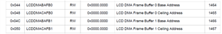
2. As datasheet mentioned: When using the LCD with EPI to interface to external memory, the external code address space 0x1000.0000 must be selected by programing the ECADR field to 0x1 in the EPI Address Map (EPIADDRMAP) register at EPI offset 0x01C. When I am using 0x1000.0000 address for SDRAM there are a lot of data corruption on screen but when I switched the address to 0x6000.0000 data corruption drops significantly but still there are pixels showing incorrect value. How to improve this.
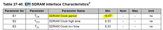
3. When I am driving EPI at 60MHz data corruption is more comparative to EPI at 120MHz. But datasheet recommend it to run at 60MHz. Why is this happening?
4. Overall I wanted to ask how to reduce the data corruption so that I can run my LCD very smoothly. Is there any register that I might have forget to set that my solve my issue.
5. And when using external SDRAM to drive LCD, how should we connect it to EPI: as External SDRAM or HOST 16 bus.
Thanks in Advance for your help.