Part Number: TMS570LS1224
Other Parts Discussed in Thread: HALCOGEN,
Hi,
I am trying to control a PWM signal generated using the N2HET.
So far I am able to see a PWM signal with a fixed frequency and a duty cycle of 25%, but I don't seem able to control this on-the-fly. I am assuming that my HalCoGen settings are valid in order to see any output at all.
As a basic test (on a LaunchpadXL board) I am programming an ADC to obtain a modifiable value, scaled to 0-100%, and I am trying to feed this into a pwmSetSignal() function to control the duty cycle.
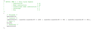
My very simple code is:
adcData_t adc_data;
adcData_t *adc_data_ptr = &adc_data;
unsigned int value;
unsigned int duty_cycle;
hetSIGNAL_t het_sig;
het_sig.duty=50;
het_sig.period = 1.000; /* 1us := 1MHz */
hetInit();
adcInit();
pwmStart(hetRAM1, pwm0);
while(1)
{
/* Get modifiable value from ADC */
adcStartConversion(adcREG1, adcGROUP1);
while(!adcIsConversionComplete(adcREG1, adcGROUP1));
adcGetData(adcREG1, 1U, adc_data_ptr);
value = (unsigned int)adc_data_ptr->value;
/* Relate the value (0-4095) to a percentage (0-100) for the PWM duty cycle */
/* The value/41 gives the duty cycle percentage, with a maximum of 99 */
duty_cycle = value / 41;
/* Update duty cycle with value from ADC */
het_sig.duty=duty_cycle;
// pwmSetSignal(hetRAM1, pwm4, het_sig);
}
When I run this code I call see on a 'scope that there is a 175.7kHz PWM signal with a 25% duty cycle.
My HalCoGen settings for pwm0 are: Period = 0.1, Duty Cycle = 10. What I am seeing bears no relation to the HalCoGen settings.
When I uncomment the call to pwmSetSignal(), the PWM output is killed completely.
My ultimate objective is to produce a PWM signal at the highest possible frequency, but (most importantly) with a controllable duty cycle over the range 0 to 99%.
Questions:
1. Can you advise where my code is incorrect and/or inadequate, please, and what is required to acchieve my objective?
2. By stepping through the code I start seeing the PWM output as soon as pwmInit() has executed. Do I need to call pwmStart()? If so why?
3. I have trawled the web to find this information so would you also point me to where I can find this (for TMS570LS1224 and N2HET and PWM)?
4. What is the best result that I can expect, in terms of maximum PWM frequency and Duty Cycle?
TIA