This thread has been locked.

If you have a related question, please click the "Ask a related question" button in the top right corner. The newly created question will be automatically linked to this question.

TM4C129ENCZAD: TM4C129x stopped driving? Cause

Part Number: TM4C129ENCZAD
Other Parts Discussed in Thread: LMFLASHPROGRAMMER, EK-TM4C129EXL, , UNIFLASH, AWR1843, AWR1843BOOST

Hello, it will be a long time, but I would like to ask you something.

1. Connect the circuit (Fig. 1) that connects TM4C129ENCZADT3 and the USB connector to the PC with a USB cable.

4834.USB and TM4C129XX.pdf

Fig 1

2. I started LMFlashProgrammer.

3. In'Configuration' of LMFlashProgrammer'set as shown in Figure 2.
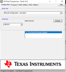
Fig 2

4. Next, in the Program Tab, set as shown in Figure 3. (The loaded file is the following file.)
C:\ti\TivaWare_C_Series-2.2.0.295\examples\boards\ek-tm4c129exl\blinky\ccs\Debug\brinky.bin
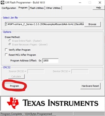
Fig.3

5. If you click the Program button (the part circled), TM4C129ENCZAD will not work.

-------------------------------------------------- -------------------------------------------------- -------------------------------
The reasons for the decision can be raised from the following two points.
(1) Crystal connected to TM4C129
The 16 MHz crystal no longer oscillates.

(2) Display of device manager
Initially, the screen shown in Fig. 4 was displayed, but it disappeared after writing the program.

Fig.4

Is there any cause you can think of?

  • Hello Kanematu-san,

    The reasons for the decision can be raised from the following two points.
    (1) Crystal connected to TM4C129
    The 16 MHz crystal no longer oscillates.

    If you did not rebuild the example then the issue is that all TivaWare examples that are built for the EK-TM4C129EXL LaunchPad use a 25MHz crystal for clock configuration as that is what is present on the LaunchPad. If you use a bad clock configuration, the device will lock up.

    You can recover the device by connecting over a JTAG probe or with an ICDI and using the Device Unlock feature either in LM Flash Programmer or with Uniflash command line.

    The following information will refer to different sections of our JTAG User's Guide: https://www.ti.com/lit/pdf/spma075

    For LM Flash Programmer, you would need to connect an ICDI circuit to your JTAG lines as outlined in Section 4.6 or Section 4.8 depending which LaunchPad you have: 

    Then in Section 5.3.1 of that document, you can see how to use LM Flash Programmer to unlock the device.

    For Uniflash Command Line, you can follow the steps in Section 5.3.2.

    When the device is unlocked, it will clear all flash content and the boot loader functionality will be restored.

    (2) Display of device manager
    Initially, the screen shown in Fig. 4 was displayed, but it disappeared after writing the program.

    Yes, once you write a program, the ROM boot loader will disappear unless the application itself invokes the boot loader to run again.

    This will happen regardless of if the device is executing code properly or not.

    That said, it's clear in this specific case that the device locked up due to incorrect clock settings.


    At this point, I think you need to suspend efforts on using the boot loader temporarily because you are using a custom board with different crystal setup and such. Start with proper code development by taking an example project, modifying it for your application needs, and load it with a debug probe through your preferred IDE to debug the code until it is working. Once you have confirmed you have working application code that runs on your custom hardware, then you can work on using the ROM boot loader to load that firmware into your device over USB.

    Best Regards,

    Ralph Jacobi

  • Hello, I will write it here because it will be long if I write it in the previous thread.

    I said

    Hello, Jacobi

    Thank you for answering the question politely.
    You should think that the reason why it doesn't work is the crystal now.

    For TM4C129ENCZAD, isn't it best to use a 25 MHz crystal?

    And if you want to reprogram with the circuit I wrote, you should copy sections 4.6,4.8,5.3.1 of the material you posted, right?

    Your reply

    Hello Kanematu-san,

    16MHz and 25MHz are both excellent choices for crystal, you just need the right software clock configuration.

    Default in TivaWare is:

    Fullscreen
    1
    2
    3
    4
    5
    6
    7
    8
    9
    //
    // Run from the PLL at 120 MHz.
    // Note: SYSCTL_CFG_VCO_240 is a new setting provided in TivaWare 2.2.x and
    // later to better reflect the actual VCO speed due to SYSCTL#22.
    //
    g_ui32SysClock = MAP_SysCtlClockFreqSet((SYSCTL_XTAL_25MHZ |
    SYSCTL_OSC_MAIN |
    SYSCTL_USE_PLL |
    SYSCTL_CFG_VCO_240), 120000000);

    You would need to use SYSCTL_XTAL_16MHZ instead of SYSCTL_XTAL_25MHZ:

    1
    2
    3
    4
    g_ui32SysClock = MAP_SysCtlClockFreqSet((SYSCTL_XTAL_16MHZ |
    SYSCTL_OSC_MAIN |
    SYSCTL_USE_PLL |
    SYSCTL_CFG_VCO_240), 120000000);
    And if you want to reprogram with the circuit I wrote, you should copy sections 4.6,4.8,5.3.1 of the material you posted, right?

    I wouldn't call it 'reprogram' as much as 'Factory Reset' the device - its a very strong reset that clears everything to default settings. And I mean everything. Any feature in the device intended to retain data across power cycles is erased to factory default, its a 100% wipe. A 'reprogram' would be simply re-writing Flash memory with new application code.

    Best Regards,

    Ralph Jacobi

  • Should I reset the order in your material?

    Will Tiva-Ware change the frequency value of the crystal after doing that?
    (If so, what file should I change to?)

  • Hello Kanematu-san,

    Clock configuration is placed at the top of void main() in the main code file.

    Best Regards,

    Ralph Jacobi

  • I decided that I needed to use B15, C15, D14, C14 to reset the IC earlier.

    However, since the IC is actually mounted on the board, the pin cannot be rewired.

    What pin can I use to reset the IC instead?
    I would appreciate it if you could tell me specifically.

  • C: \ ti \ TivaWare_C_Series-2.2.0.295 \ examples \ boards \ ek-tm4c129exl \ blinky \ ccs \ Debug \ blinky.bin

    What kind of Binary file is the above file?

  • The file you're talking about is this file in a hierarchy, right?

    C: \ ti \ TivaWare_C_Series-2.2.0.295 \ examples \ peripherals \ rom \ rom_mapped.c

  • Hello Kanematu-san,

    I decided that I needed to use B15, C15, D14, C14 to reset the IC earlier.

    However, since the IC is actually mounted on the board, the pin cannot be rewired.

    What pin can I use to reset the IC instead?

    If you don't have the JTAG pins routed, the IC cannot be reset. The board is unrecoverable if you cannot access those pins.

    JTAG should never be excluded from routing for development designs. Final designs can exclude as a security measure, but that should only be done after software development is concluded.

    Best Regards,

    Ralph Jacobi

  • Hello Kanematu-san,

    C: \ ti \ TivaWare_C_Series-2.2.0.295 \ examples \ boards \ ek-tm4c129exl \ blinky \ ccs \ Debug \ blinky.bin

    What kind of Binary file is the above file?

    The file you're talking about is this file in a hierarchy, right?

    C: \ ti \ TivaWare_C_Series-2.2.0.295 \ examples \ peripherals \ rom \ rom_mapped.c

    I apologize but I cannot walk you through every little detail of our software kit, there is extensive documentation in the docs folder about all our APIs and you can also use windows search in driverlib folder to find which files specific APIs belong to quickly and find the code comments for those APIs

    MAP_ and ROM_ functions have Flash versions where you can get full details and source code by simply dropping the MAP_ or ROM_ tag so for example you can search driverlib folder for SysCtlClockFreqSet to find the function details.

    Given your unfamiliarity with the devices, you may want to consider viewing our training videos:

    The first for the TM4C123x family but it has more fundamentals applicable to all TM4C devices and the second delves more into the TM4C129x devices and their added feature set.

    I hope by providing you this guidance and resources you will be able to better navigate our TivaWare collateral to find what you need.

    Best Regards,

    Ralph Jacobi

  • Hello, thank you for the detailed explanation.

    I made this circuit with reference to AWR1843 Boost.
    If I want to reset the U6 used for AWR1843 Boost, what method should I use to reset it?

  • Hello Kanematu-san,

    I do not support AWR1843BOOST. For a board like that, the TM4C device is typically used as an XDS110 emulator to avoid the need for a JTAG debug probe when doing quick evaluation. You shouldn't need it on a production solution for that device.

    I would suggest you make a post to the Radar team using part number AWR1843BOOST and ask them how they recommend you handle your custom board design. I would anticipate you can scratch the TM4C from your BOM and save a lot of cost!

    Best Regards,

    Ralph Jacobi