This thread has been locked.

If you have a related question, please click the "Ask a related question" button in the top right corner. The newly created question will be automatically linked to this question.

TMDSEMU110-U: AUX port help

Part Number: TMDSEMU110-U

I have the XDS110 plugged in to my PC via USB. I have the AUX port breakout board connected to the AUX port and the Debug port connections are not connected.

I expected to be able to measure 5V at the TGTSUPPLYOUT pins but I'm not seeing any voltage. I have tried two different xds110 probes. Do I need to do something to activate the Aux port functionality?

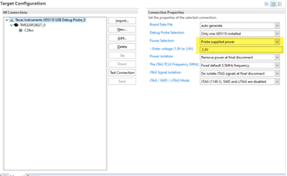
  • You will need to configure the TGTSUPPLYOUT in the ccxml file in CCS. 

    Double click the ccxml target file and click on the advanced tab. 

    Then click on the XDS110 emulator in the left box and it should pull up the below dialogue, I've highlighted the fields that need to be modified to get target power out. 

    Note that the range is capped at 3.6V and will only activate when you initiate a debug session(launch the .ccxml)

    Best,

    Matthew

  • Note that the range is capped at 3.6V and will only activate when you initiate a debug session(launch the .ccxml)

    While I haven't tried it, looking at the XDS110 documentation shows some other options:

    1. The  "Power Isolation" in the CCS Target Configuration the option "Keep power at final disconnect" will continue supplying power to the target even after the debug session has terminated. See Section 3.1.2.2

    2. The dbgjtag command line utility allows the XDS110 power supply voltage to be changed and turned on/off outside of CCS. See Section 3.7.3.3 - Power. The help shows the range of supply voltages:

    $ /home/mr_halfword/ti/ccs1120/ccs/ccs_base/common/uscif/dbgjtag -f @xds110 -Y help
    
      The '-Y' major option supports debug probe configuration
      
      This option has a sub-argument that is a comma separated list
      of a command and zero or more parameters. The parameters consist
      of 'name=value' pairs that may be listed in any order.
      
      -Y help
         Print this brief help.
      
      -Y reset,system=boolean,jtag=boolean,logfile=boolean
         Reset a debug probe and its target via the SRSTn/TRSTn pins.
      
      -Y emupins,jtagboot=string,powerboot=string,emuoutput=string
         Select the bootmode and default values for the EMU1-0 pins.
      
      -Y jtagpins,isolate=enable/disable,loopback=string,linkdelay=string,
                  tdoedge=string,tdiedge=string
         Select the configuration of the JTAG pins.
      
      -Y gpiopins,config=number,write=number,read=boolean,mask=number
         Configure, write, and read the user GPIO pins. (XDS110 only).
      
      -Y unlock,mode=string
         Do unlock procedure on target device. The supported modes are 
         mode=msp432e4. (XDS100, XDS110, and XDS200).
         mode=tiva. (XDS100, XDS110, and XDS200).
      
      -Y blink
         Blink LEDs on debug probe to identify which probe is being 
         accessed. (XDS110 only),
      
      -Y power,supply=on/off,voltage=number
         Configure power to the target (XDS110 only),
         voltage=any value in Volts between 1.8V and 3.6V.
    

  • Ah, should've thought to look at the ccxml. I was trying to use it standalone without ccs. Thanks!

  • Thanks for the link. I wish these https://software-dl.ti.com/ pages were linked from the product page or there was a search function on that site for finding  documentation. Until then I'll have to try to remember to include that domain name in my web searches.