This thread has been locked.

If you have a related question, please click the "Ask a related question" button in the top right corner. The newly created question will be automatically linked to this question.

RM44L520: Issue configuring SCI3 communication

Part Number: RM44L520
Other Parts Discussed in Thread: HALCOGEN,

 Hello, 

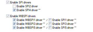
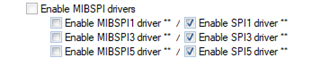
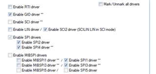
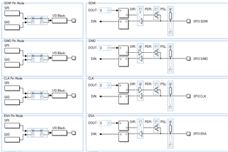
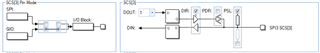
I am trying to configure SCI3 to communication with another internal device using pins 36,38,35, and 34. I have configured them all in halcogen under the SPI3 tab and have selected the SPI3 driver in the driver select menu. My confusion is coming from the fact that the documentation for this processor only lists registers labeled as MibSPI3 not just SPI3. Am I able to use just SPI on these pins or do I have to use MibSPI? I am porting over code to service a separate processor so If I can continue to use SPI that would be preferable. 


  • Hi Andrew,

    The SPI3/MibSPI3 module does supports both Multi-buffered mode (mibspi) and compatibility mode (spi). If you wants to use mibspi mode, please set "MSPIENA" bit or check "MibSPI" on HAL GUI:

    If the SPI compatibility mode is used, please check SPIx in HAL GUI or clear "MSPIENA" bit:


  • Thank you for the response. I have the SPI mode checked.

    I also have the ports configured for SPI3.

    And I am using the following function to send the SPI signal out 

    Does anything seem wrong here?

  • I believe my issue has to do with a hardware delay that is implemented before the message is sent. I am setting the follow registers to create a hardware delay:

    When I look at the values at rtiREG1's address I see the following:

    It seems as though the only updates that are taking place are from the RTOS tick. Is there something else that needs to be enabled for this registers to be updated properly?

  • Does anything seem wrong here?

    You said that the MIBSPI3nCS[0] (pin 38) is used, but the snapshot shows that the SCS[3] is used (GIO mode).

    Does hpiCurrentLoop_SetCS(...) pull up or down the nCS[3] pin or nCS[0] pin?

  • Is there something else that needs to be enabled for this registers to be updated properly?

    Do you use the freeRTOS generated by HALCoGen? 

    The RTI is configured in "static void prvSetupTimerInterrupt(void)". Only compare 0 is enabled. If you want to use compare 2, you can enabled it in this function.

  • The processor I am using does not have a FreeRTOS version included in halcogen so I had to follow the steps in the app note to configure FreeRTOS with halcogen manually. What would I need to add to that function to enable the use of compare 2?

  • Hi Andrew,

    The HALCoGen does have an freeRTOS example for RM44L520 package:

    BTW, in the freeRTOS example, HALCoGen doesn't generate rti.c and rti.h, and only compare 0 (for OS ticks) is configured in the os_port.c file. 

    If you want to use other RTI compares, you need to add your code to configure them. 

  • That is for the PGE package while I am using the PZ package. I have been trying to manually configure the RTI channel I would like to use but I haven't been having any luck. Is there any example code of this being done? 

  • Hi Andrew,

    You can insert your own code to prvSetupTimerInterrupt(void) to enable other RTI compares. For example:


    static void prvSetupTimerInterrupt(void)
    {
          /* Disable timer 0. */
         portRTI_GCTRL_REG &= 0xFFFFFFFEUL;

         /* Use the internal counter. */
         portRTI_TBCTRL_REG = 0x00000000U;

         /* COMPSEL0 will use the RTIFRC0 counter. */
         portRTI_COMPCTRL_REG = 0x00000000U;

         /* Initialise the counter and the prescale counter registers. */
         portRTI_CNT0_UC0_REG = 0x00000000U;
         portRTI_CNT0_FRC0_REG = 0x00000000U;

          /* Set Prescalar for RTI clock. */
         portRTI_CNT0_CPUC0_REG = 0x00000001U;
         portRTI_CNT0_COMP0_REG = ( configCPU_CLOCK_HZ / 2 ) / configTICK_RATE_HZ;
         portRTI_CNT0_UDCP0_REG = ( configCPU_CLOCK_HZ / 2 ) / configTICK_RATE_HZ;

         portRTI_CNT0_COMP1_REG = ( configCPU_CLOCK_HZ / 2 ) / configTICK_RATE_HZ / 10;    //QJ added to configure compare 1
         portRTI_CNT0_UDCP1_REG = ( configCPU_CLOCK_HZ / 2 ) / configTICK_RATE_HZ / 10;     //QJ added to configure compare 1

          /* Clear interrupts. */
         portRTI_INTFLAG_REG = 0x0007000FU;
         portRTI_CLEARINTENA_REG = 0x00070F0FU;

         /* Enable the compare 0 interrupt. */
         portRTI_SETINTENA_REG = 0x00000001U;

         portRTI_SETINTENA_REG |= 0x00000002U;      //QJ added  to enable INT of configure compare 1

         portRTI_GCTRL_REG |= 0x00000001U;
    }

    and

  • To make RTI compare 1 (configured in my last post), you need to enable the RTI COmpare 1 channel in VIM module:

    and give the ISR name for RTI compare 1, for example myTestISR

    Since the HAL (freeRTOS example) doesn't generate rti.c and rti.h, the myTestIRS is not generated by HAL, you have to write it by yourself:

    void myTestISR(void);

    void myTestISR(void) {
           /* Clear interrupt flag.*/
           *((volatile uint32_t *) 0xFFFFFC88) = 2U;
           ... ...
    }

    If you only use the polling mode, you don't need to define this ISR.

  • I have configured my code exactly as you have it posted in the last two messages and RTIFRC1 is still never increasing. How could I go about solving this?

  • I have configured the registers as shown:

    I have enabled an interrupt on channel 1:

    I am clearing the interrupt flag in the interrupt:

    I am configuring a delay:

    And I am getting no change at any point on the RTIFRC1 register. 

  • Hi Andrew,

    Before you read the value from the FRC1 register, have you enabled the counter1?

    Please review the RTI chapter in Device Technical Reference Manual. 

  • Thank you, I didn't realize that I needed to enable counter 1 to use RTIFRC1 as it was configured to use counter 0.