This thread has been locked.

If you have a related question, please click the "Ask a related question" button in the top right corner. The newly created question will be automatically linked to this question.

TMS570LC4357: Is it possible to use the two pins of I2C1 on the LAUNCHPAD XL2 development board to communicate directly with other I2C devices?

Part Number: TMS570LC4357
Other Parts Discussed in Thread: HALCOGEN

Hi team,

Here's an issue from the customer may need your help:

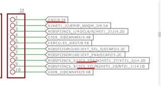
Using the LAUNCHXL2 570LC43 development board, the customer attempts to communicate with I2C devices on other boards using the two pins of I2C1 that are brought out on the board. J2 numbers 1 (GND) 8 and 9 are used in the figure below and are connected to the GND and I2C pins on the other boards, respectively.

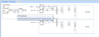
HALCoGen configuration is as follows:

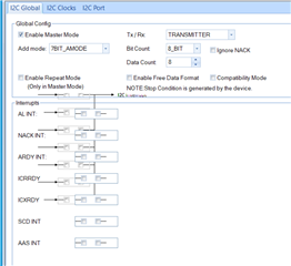
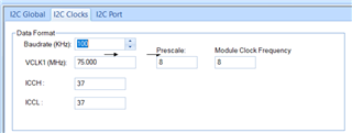
The customer calls the i2cInit() function in the main function and tries to communicate with the device, but the program is stuck in the i2cIsMasterReady or i2cSendByte function. Grabbed both pins with an oscilloscope and did not see any waveforms. Can it be connected directly like this?

Could you help check this case? Thanks.

Best Regards,

Cherry

  • Hi Cherry,

    #1, Are I2C SCL and SDA pulled up through resistors? The TMS570 development board doesn't have external pull-up resistors on I2C lines.

    Both I2C SCL and SDA lines are "open drain", so the I2C module can drive SCL and SDA Low, but cannot drive them High. For those two lines to be able to go high you must provide external pull-up resistors.

    #2, On TMS570LC43x device, the I2C signals are multiplexed with MibSPI signals, and the pins are used for MibSPI by default. Did you configure the pinmux?


  • Hi,

    Thanks for your help.

    #1, Are I2C SCL and SDA pulled up through resistors? The TMS570 development board doesn't have external pull-up resistors on I2C lines.

    The slave device to be communicated has a pull-up on the board and the customer can communicate directly with that device using another development board (verified).

    #2, On TMS570LC43x device, the I2C signals are multiplexed with MibSPI signals, and the pins are used for MibSPI by default. Did you configure the pinmux?

    No pinmux was configured before and regarding the pinmux, the MibSPI module is not enabled in Driver Enable, only I2C1 is enabled, do they still need to configure the pinmux?

    Also, the customer has followed your response to configure pinmux and call muxInit() in program. However, communication is still not possible and i2cIsMasterReady is still unable to return.

    Thanks and regards,

    Cherry

  • the MibSPI module is not enabled in Driver Enable, only I2C1 is enabled, do they still need to configure the pinmux?

    Yes, the pinmux should be configured regardless of if the module is enable or not. 

    communication is still not possible and i2cIsMasterReady is still unable to return.

    After the i2cSendByte() is called, do you see the clock signal on SCL line and data waveform on SDA line?

  • Hi QJ,

    The customer has PINMUX configured in HALCoGen, do they need to call muxInit() during program initialization?

    do you see the clock signal on SCL line

    No clock signal on SCL line and data waveform on SDA line have been seen. 

    Thanks and regards,

    Cherry

  • Hi QJ,

    May I know is there any follow up?

    Thanks and regards,

    Cherry

  • do they need to call muxInit() during program initialization?

    The muxInit() is called in systemInit() in HAL code. The customer does not need to call this function again.

    After the I2C slave is connected, are SCL and SDA at HIGH level? If not, the pull-up on I2C slave board doesn't work. 

    If the SCL and SDA are pulled up properly, the two lines should be HIGH, when you call i2CStart() API, the I2C module will issue a START condition and send the slave address.