This thread has been locked.

If you have a related question, please click the "Ask a related question" button in the top right corner. The newly created question will be automatically linked to this question.

TMS570LS1227: Bootloader to Application Jump

Part Number: TMS570LS1227

Hello TI Team,

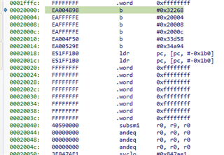
I am working on Bootloader design of  TMS750Ls1227 part number. Once the Application hex file is flashed in memory by Bootloader, Jump to Application is done. But the Application is not executing properly.

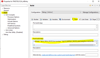
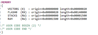
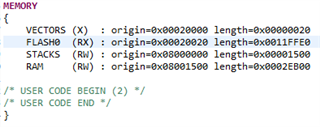
From the previous articles on Forum, it was found some changes to be done in cmd file and intvec.asm file. But after taking into those guidelines into consideration, still the same problem persist.

What should be the correct way of writing cmd and intvec.asm file for both Bootloader and Application? Or any other changes ?

  • Vijay,

    The TI bootloader example supports application only in binary format. You can generate binary file using CCS:

    Post-build steps

    "${CCS_INSTALL_ROOT}/utils/tiobj2bin/tiobj2bin" "${BuildArtifactFileName}" "${BuildArtifactFileBaseName}.bin" "${CG_TOOL_ROOT}/bin/armofd" "${CG_TOOL_ROOT}/bin/armhex" "${CCS_INSTALL_ROOT}/utils/tiobj2bin/mkhex4bin" 

    The bootloader example doesn't support other binary formats or hex formats.

  • Hello QJ,

    I apologize for late reply.

    I have designed my own Bootloader and I am not using the TI Bootloader example.

    Is it that, only binary files are required. Cant we use Hex files ?

  • Hi Vijay,

    Yes, you can develop your own bootloader for downloading a HEX format files. 

    If the application is programmed to the flash starting at 0x10000, the origin of VECTORS in your linker cmd script should be 0x10000 too, and the origin of FLASH0 in your linker CMD becomes 0x10020.

    The destination address of branch instruction in your bootloader should be 0x10000. For example:

    ((void (*)(void))0x10000)();

  • Hi QJ

    as per your suggestions,

    My Bootloader cmd file is 

    and Application cmd file is 

    The Hex file of application is flashed successfully using bootloader firmware.

    ((void (*)(void))0x20000)() is not working . It is not jumping to application 20000 address 

  • Also instead of (void (*)(void))0x20000)() 

    I tried with 

    asm(" mov r14, #0x20000");
    asm(" bx r14");

    Using this there is jump to 20000 location but then fails.....probably undef entry

    share the link of TI Bootloader example

  • Sorry, I missed one left parenthesis in my prior message. It should be:

     ((void (*)(void))0x20000)();

    but then fails.....probably undef entry

    1. please double check that 0x20000 has been programmed correctly. It should look like: 0xEA......

    2. is the ECC calculated and programmed when you programmed the application to flash? 

  • Can you please elaborate on ECC ? how it is to be done ?

  • please provide the link of TI Bootloader example on CAN....

  • Debug snap for location 0x20000 after jump using 

    asm(" mov r14, #0x20000");
    asm(" bx r14");

    assembly instruction

  • hey Hi QJ Wang,

    any update?

  • Hi QJ, 

    I am regering to the pdf CAN Bus Bootloader for HerculesTm Microcontrollers.pdf

    as per that i have made the changes in cmd file as below for both bootloader and application 

    After jumping to application from bootloader ,,  it goes to 0x0c address i.e. prefetchentry

    please have a look at cmd linker files 

    sys_link_app.txt
    /* Linker Settings */
    --retain="*(.intvecs)"
    /* Memory Map */
    MEMORY
    {
    	/* Add a vfill directive to the end of each line that maps to Flash */
    	VECTORS (X) : origin=0x00020000 length=0x00000020 vfill = 0xffffffff
    	FLASH0 (RX) : origin=0x00020020 length=0x0011ffE0 vfill = 0xffffffff
        STACKS  (RW) : origin=0x08000000 length=0x00001500
        RAM     (RW) : origin=0x08001500 length=0x0002EB00
    	/* USER CODE BEGIN (3) */
    	#if 1
    	/* Add memory regions corresponding to the ECC area of the flash bank */
    	ECC_VEC (R) : origin=(0xf0400000 + (start(VECTORS) >> 3))
    	length=(size(VECTORS) >> 3)
    	ECC={algorithm=algoL2R5F021, input_range=VECTORS}
    	ECC_FLA0 (R) : origin=(0xf0400000 + (start(FLASH0) >> 3))
    	length=(size(FLASH0) >> 3)
    	ECC={algorithm=algoL2R5F021, input_range=FLASH0 }
    	#endif
    	/* USER CODE END */
    }
    /* USER CODE BEGIN (4) */
    /* Add an ECC {} directive describing the algorithm that matches the device */
    ECC
    {
    	algoL2R5F021 : address_mask = 0xfffffff8 /*Address Bits 31:3 */
    	hamming_mask = R4 /*Use R4/R5 build in Mask */
    	parity_mask = 0x0c /*Set which ECC bits are Even & Odd parity */
    	mirroring = F021 /*RM57Lx and TMS570LCx are build in F021*/
    }
    /* USER CODE END */
    SECTIONS
    {
        .intvecs : {} > VECTORS
        .text    : {} > FLASH0
        .const   : {} > FLASH0
        .cinit   : {} > FLASH0
        .pinit   : {} > FLASH0
        .bss     : {} > RAM
        .data    : {} > RAM
        .sysmem  : {} > RAM
    
    
    /* USER CODE BEGIN (6) */
    /* USER CODE END */
    
    }
    
    sys_link_boot.txt
    /* Linker Settings */
    --retain="*(.intvecs)"
    /* Memory Map */
    MEMORY
    {
    	/* Add a vfill directive to the end of each line that maps to Flash */
    	VECTORS (X) : origin=0x00000000 length=0x00000020 vfill = 0xffffffff
    	FLASH0 (RX) : origin=0x00000020 length=0x001FFFE0 vfill = 0xffffffff
       STACKS  (RW) : origin=0x08000000 length=0x00001500
        RAM     (RW) : origin=0x08001500 length=0x0002EB00
    	/* USER CODE BEGIN (3) */
    	#if 1
    	/* Add memory regions corresponding to the ECC area of the flash bank */
    	ECC_VEC (R) : origin=(0xf0400000 + (start(VECTORS) >> 3))
    	length=(size(VECTORS) >> 3)
    	ECC={algorithm=algoL2R5F021, input_range=VECTORS}
    	ECC_FLA0 (R) : origin=(0xf0400000 + (start(FLASH0) >> 3))
    	length=(size(FLASH0) >> 3)
    	ECC={algorithm=algoL2R5F021, input_range=FLASH0 }
    	#endif
    	/* USER CODE END */
    }
    /* USER CODE BEGIN (4) */
    /* Add an ECC {} directive describing the algorithm that matches the device */
    ECC
    {
    	algoL2R5F021 : address_mask = 0xfffffff8 /*Address Bits 31:3 */
    	hamming_mask = R4 /*Use R4/R5 build in Mask */
    	parity_mask = 0x0c /*Set which ECC bits are Even & Odd parity */
    	mirroring = F021 /*RM57Lx and TMS570LCx are build in F021*/
    }
    /* USER CODE END */
    SECTIONS
    {
        .intvecs : {} > VECTORS
     /*   .TI.ramfunc align(32) : {	-l F021_API_CortexR4_BE_V3D16.lib(.text) }
    								LOAD=FLASH0, RUN=RAM,
    								LOAD_START(RamfuncsLoadStart),
    								RUN_START(RamfuncsRunStart),
    								SIZE(RamfuncsLoadSize)
       */
        .text    : {} > FLASH0
        .const   : {} > FLASH0
        .cinit   : {} > FLASH0
        .pinit   : {} > FLASH0
        .bss     : {} > RAM
        .data    : {} > RAM
        .sysmem  : {} > RAM
    
    
    /* USER CODE BEGIN (6) */
    /* USER CODE END */
    
    
    	GROUP
    	{
           .TI.ramfunc
           { -l F021_API_CortexR4_BE_V3D16.lib(.text)}
    
    	} 					LOAD = FLASH0,
    						RUN = RAM,
    						LOAD_START(RamfuncsLoadStart),
    						RUN_START(RamfuncsRunStart),
    						SIZE(RamfuncsLoadSize),
    						ALIGN(4)
    }
    

  • Hi Vijay,

    The application is loaded by Bootloader, and programmed to flash using F021 flash APIs. The ECC of application code is generated using F021 Flash APIs. Please don't use linker script to generate ECC for Application firmware.

    Fapi_issueProgrammingCommand((uint32_t *)dst,
                                                            (uint8_t *)src,
                                                            (uint32_t) bytes,
                                                             0,
                                                             0,
                                                            Fapi_AutoEccGeneration);