This thread has been locked.

If you have a related question, please click the "Ask a related question" button in the top right corner. The newly created question will be automatically linked to this question.

AM2634: EDMA3 ParRAM Configuration Question

Part Number: AM2634

Hi,

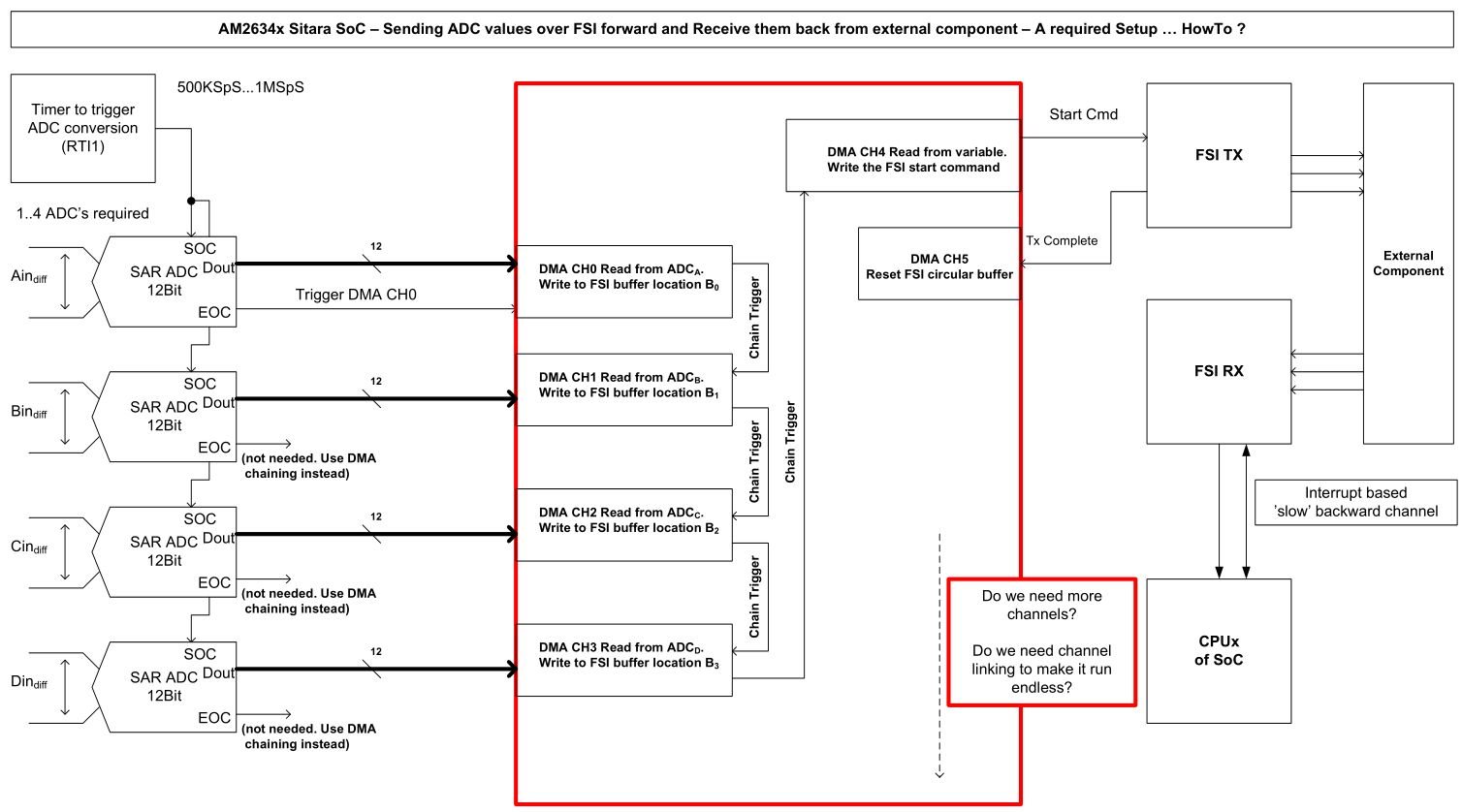
I need to transfer a couple (4) of sampled values from four ADC's over a fast serial link channel to a companion chip using the EDMA and the FSI from the AM2634. Once configured this data transfer of these sampled values has to run endless without any further CPU intervention. In this context the CPU code is used for configuration purpose only and for exception handling in case of troubles.

The setup / configuration is done the following way:

- The ADC's do sample the voltage on one differential input (named Ai, Bi, Ci and Di). The sampled value is stored in one of the result register for each ADC. The sampling interval shall be ~ 2usec.

- ADC_A (from input Ai) shall trigger the EDMA channel (CH0) through its end of conversion event (EOC). This channel shall transfer the sampled value SAMPLE_A into the data RAM section of the FSI channel. Once this single word transfer completes it shall 'trigger' (using 'chaining' ?) the next EDMA channel (CH1) to do the very same but this time for the sample 'SAMPLE_B' from ADC_B representing Bi. The destination address for this single word transfer is up by two bytes in order to align the sampled value of Bi just above SAMPLE_A of Ai. This mechanism repeats for Ci and Di using EDMA channels CH2 and CH3.

- EDMA channel CH3 'triggers' CH4 which basically writes the code/cmd-word into the appropriate FSI channel to start transferring the four sampled values to the external companion chip.

- Once the FSI transmission completes a fifth DMA channel (CH5) shall be used to reset the internal RAM address pointer within the Tx FSI channel used, in order to guarantee that the next four samples are being xferred correctly. The data RAM within the FSI channel is not a FIFO. Therefore an address pointer addressing up to 16 words needs to be reseted each time after the current transmission completes. Otherwise the position within the data RAM of the Tx FSI would be different.

(A block diagram is attached that show what I try to accomplish)

So far so good. Now the questions:

Q1: How do I need to setup the ParRAM of the EDMA to accomplish this? Especially how do I configure the option register within the ParRAM?

Q2: Do I need channel linking, since it has to run endless, once setup?

Q3: Is there an example that shall be used in order to accomplish this setup?

Q4: The TRM of the AM2634 is not complete in respect to the EMDA description. I did find another document from TI. "KeyStone Architecture
Enhanced Direct Memory Access (EDMA3) Controller User's Guide" (sprugs5b.pdf) Can this be used for the EDMA3 on the AM2634?

br

Markus

  • I tried to simplify the above architecture using two DMA channels. These two channels shall be chained and each of them shall be linked to create the continuous mode on the EDMA3. I am not sure if I do understand it correctly. In the setup code shown below I use dmaCh0 and dmaCh1. dmaCh0 shall be triggered from the EoC flag from an ADC. dmaCh0 shall read the result register from the ADC and write it to the beginning of the ring-buffer for FSI Tx Channel 2. After completion of this operation it shall 'trigger' the chained DMA channel dmaCh1. dmaCh1 is used to start the FSI Tx transfer. This is accomplished by writing a start-code word into the control register of the FSI Tx 2 transmitter unit.

    The scenario described above shall repeat a number of times, then channel linking for both the dmaCh0 and the dmaCh1 shall reload their Param Sets in order to get it continuous.

    When I do run the code shown below sometimes I does run. However the enabling of the DMA trigger seems to be a problem. Maybe also a configuration issue of the whole EDMA. Any help or hint would be appreciated.

    br

    Markus

    uint16_t App_dmaConfigure(
            uint32_t dac_base, uint16_t table_size, EDMA_Handle dma_handle,
            uint32_t dma_ch, uint32_t adc_base)
    {

        uint32_t            baseAddr, regionId;

        EDMACCPaRAMEntry    edmaParam0, edmaParam32; // Parameter set for 'dmaCh0'
        EDMACCPaRAMEntry    edmaParam1, edmaParam33; // Parameter set for 'dmaCh1'

        uint32_t            dmaCh0, tcc0, param0, param32; // resource ref. for Ch0
        uint32_t            dmaCh1, tcc1, param1, param33; // resource ref. for Ch1

        int32_t             testStatus = SystemP_SUCCESS;

        baseAddr = EDMA_getBaseAddr(gEdmaHandle[0]);
        DebugP_assert(baseAddr != 0);

        regionId = EDMA_getRegionId(gEdmaHandle[0]);
        DebugP_assert(regionId < SOC_EDMA_NUM_REGIONS);

        /* DMA Channel 0 and the parameter set 'param32' for 'channel linking' to.
         * make it a continuous mode channel.
         */

        dmaCh0 = dma_ch;
        testStatus = EDMA_allocDmaChannel(gEdmaHandle[0], &dmaCh0);
        DebugP_assert(testStatus == SystemP_SUCCESS);

        tcc0 = EDMA_RESOURCE_ALLOC_ANY;
        testStatus = EDMA_allocTcc(gEdmaHandle[0], &tcc0);
        DebugP_assert(testStatus == SystemP_SUCCESS);

        param0 = EDMA_RESOURCE_ALLOC_ANY;
        testStatus = EDMA_allocParam(gEdmaHandle[0], &param0);
        DebugP_assert(testStatus == SystemP_SUCCESS);

        param32 = EDMA_RESOURCE_ALLOC_ANY; // channel linking param ref for dmaCh0
        testStatus = EDMA_allocParam(gEdmaHandle[0], &param32);
        DebugP_assert(testStatus == SystemP_SUCCESS);

        /* Request channel 0 */
        EDMA_configureChannelRegion(baseAddr, regionId, EDMA_CHANNEL_TYPE_DMA,
             dmaCh0, tcc0, param0, EDMA_TEST_EVT_QUEUE_NO);

        /* Disable the interrupt for the channel to transfer in polled mode */
        EDMA_disableEvtIntrRegion(baseAddr, regionId, dmaCh0);

        /* DMA Channel 1. This is the one to be chained to from channel 0.
         *
         */
        dmaCh1 = EDMA_RESOURCE_ALLOC_ANY;
        testStatus = EDMA_allocDmaChannel(gEdmaHandle[0], &dmaCh1);
        DebugP_assert(testStatus == SystemP_SUCCESS);

        tcc1 = EDMA_RESOURCE_ALLOC_ANY;
        testStatus = EDMA_allocTcc(gEdmaHandle[0], &tcc1);
        DebugP_assert(testStatus == SystemP_SUCCESS);

        param1 = EDMA_RESOURCE_ALLOC_ANY;
        testStatus = EDMA_allocParam(gEdmaHandle[0], &param1);
        DebugP_assert(testStatus == SystemP_SUCCESS);

        param33 = EDMA_RESOURCE_ALLOC_ANY;
        testStatus = EDMA_allocParam(gEdmaHandle[0], &param33);
        DebugP_assert(testStatus == SystemP_SUCCESS);

        /* Request channel 1 */
        EDMA_configureChannelRegion(baseAddr, regionId, EDMA_CHANNEL_TYPE_DMA,
             dmaCh1, tcc1, param33, EDMA_TEST_EVT_QUEUE_NO);

        /* Disable the interrupt for the channel to transfer in polled mode */
        EDMA_disableEvtIntrRegion(baseAddr, regionId, dmaCh1);

        /* Program Param Set edmaParam0, edmaParam32 */
        EDMA_ccPaRAMEntry_init(&edmaParam0);  // Clear the parameter sets
        EDMA_ccPaRAMEntry_init(&edmaParam32); // ..

        edmaParam0.srcAddr       = (uint32_t) SOC_virtToPhy((void *)(adc_base+CSL_ADC_RESULT_ADCRESULT0));
        edmaParam0.destAddr      = (uint32_t) SOC_virtToPhy((void *)(CONFIG_FSI_TX2_BASE_ADDR + FSI_TX_DBUF_BASE_ADDR));
        edmaParam0.aCnt          = (uint16_t) 2;
        edmaParam0.bCnt          = (uint16_t) table_size;
        edmaParam0.cCnt          = (uint16_t) 1;
        edmaParam0.bCntReload    = 0;
        edmaParam0.srcBIdx       = (int16_t) 0;
        edmaParam0.destBIdx      = (int16_t) 0; // Always write to the same location
        edmaParam0.srcCIdx       = (int16_t) 0;
        edmaParam0.destCIdx      = (int16_t) 0;
        edmaParam0.linkAddr      = 0xFFFFU;
        edmaParam0.opt           = (EDMA_OPT_TCINTEN_MASK | EDMA_OPT_TCCHEN_MASK |
                                    ((((uint32_t)tcc0) << EDMA_OPT_TCC_SHIFT) & EDMA_OPT_TCC_MASK));

        EDMA_setPaRAM(baseAddr, param0, &edmaParam0);

        // Used for 'channel linking' of dmaCh0
        edmaParam32.srcAddr       = (uint32_t) SOC_virtToPhy((void *)(adc_base+CSL_ADC_RESULT_ADCRESULT0));
        edmaParam32.destAddr      = (uint32_t) SOC_virtToPhy((void *)(CONFIG_FSI_TX2_BASE_ADDR + FSI_TX_DBUF_BASE_ADDR));
        edmaParam32.aCnt          = (uint16_t) 2;
        edmaParam32.bCnt          = (uint16_t) table_size;
        edmaParam32.cCnt          = (uint16_t) 1;
        edmaParam32.bCntReload    = 0;
        edmaParam32.srcBIdx       = (int16_t) 0;
        edmaParam32.destBIdx      = (int16_t) 0; // Always write to the same location
        edmaParam32.srcCIdx       = (int16_t) 0;
        edmaParam32.destCIdx      = (int16_t) 0;
        edmaParam32.linkAddr      = 0xFFFFU;
        edmaParam32.opt           = (EDMA_OPT_TCINTEN_MASK | EDMA_OPT_TCCHEN_MASK |
                                     ((((uint32_t)tcc0) << EDMA_OPT_TCC_SHIFT) & EDMA_OPT_TCC_MASK));

        EDMA_setPaRAM(baseAddr, param32, &edmaParam32);
        
        EDMA_linkChannel(baseAddr, param0, param32);
        EDMA_linkChannel(baseAddr, param32, param32);

        /* Program Param Set edmaParam1, edmaParam33 */
        EDMA_ccPaRAMEntry_init(&edmaParam1);  // Clear the parameter sets
        EDMA_ccPaRAMEntry_init(&edmaParam33); // ..

        edmaParam1.srcAddr       = (uint32_t) SOC_virtToPhy((void *)(&gFSICh2TxStartWord4DMA));
        edmaParam1.destAddr      = (uint32_t) SOC_virtToPhy((void *)(CONFIG_FSI_TX2_BASE_ADDR + CSL_FSI_TX_CFG_TX_FRAME_CTRL));
        edmaParam1.aCnt          = (uint16_t) 2;
        edmaParam1.bCnt          = (uint16_t) table_size;
        edmaParam1.cCnt          = (uint16_t) 1;
        edmaParam1.bCntReload    = 0;
        edmaParam1.srcBIdx       = (int16_t) 0;
        edmaParam1.destBIdx      = (int16_t) 0; // Always write to the same location
        edmaParam1.srcCIdx       = (int16_t) 0;
        edmaParam1.destCIdx      = (int16_t) 0;
        edmaParam1.linkAddr      = 0xFFFFU;
        edmaParam1.opt           = (EDMA_OPT_TCINTEN_MASK | EDMA_OPT_TCCHEN_MASK |
                                    ((((uint32_t)tcc1) << EDMA_OPT_TCC_SHIFT) & EDMA_OPT_TCC_MASK));

        EDMA_setPaRAM(baseAddr, param1, &edmaParam1);

        edmaParam33.srcAddr       = (uint32_t) SOC_virtToPhy((void *)(&gFSICh2TxStartWord4DMA));
        edmaParam33.destAddr      = (uint32_t) SOC_virtToPhy((void *)(CONFIG_FSI_TX2_BASE_ADDR + CSL_FSI_TX_CFG_TX_FRAME_CTRL));
        edmaParam33.aCnt          = (uint16_t) 2;
        edmaParam33.bCnt          = (uint16_t) table_size;
        edmaParam33.cCnt          = (uint16_t) 1;
        edmaParam33.bCntReload    = 0;
        edmaParam33.srcBIdx       = (int16_t) 0;
        edmaParam33.destBIdx      = (int16_t) 0; // Always write to the same location
        edmaParam33.srcCIdx       = (int16_t) 0;
        edmaParam33.destCIdx      = (int16_t) 0;
        edmaParam33.linkAddr      = 0xFFFFU;
        edmaParam33.opt           = (EDMA_OPT_TCINTEN_MASK | EDMA_OPT_TCCHEN_MASK |
                                     ((((uint32_t)tcc1) << EDMA_OPT_TCC_SHIFT) & EDMA_OPT_TCC_MASK));

        EDMA_setPaRAM(baseAddr, param33, &edmaParam33);

        EDMA_linkChannel(baseAddr, param1, param33);
        EDMA_linkChannel(baseAddr, param33, param33);

        // Set params for chain transfer. dmaCh0 to be chained to dmaCh1
        EDMA_chainChannel(baseAddr, param0, dmaCh1, (EDMA_OPT_TCCHEN_MASK | EDMA_OPT_ITCCHEN_MASK));

        // Enable the triggers for all the channels.
        EDMA_enableTransferRegion(baseAddr, regionId, dmaCh0, EDMA_TRIG_MODE_MANUAL); // needed ???
        EDMA_enableTransferRegion(baseAddr, regionId, dmaCh0, EDMA_TRIG_MODE_EVENT);
        return testStatus;
    }

  • Hi Markus,

    Is the DMA Trigger XBAR configured to route the FSI triggers to the corresponding DMA channels ? You may use the SysCfg configuration of "FSI_LOOPBACK_DMA" example as a reference for the same.

    Each ADC EOC should trigger corresponding DMA channel when multiple ADC channels are being used. DMA channels should not be chained together for transferring ADC results. The issue is that synchronization can't be guaranteed between ADC conversion and DMA transfer. You can chain the EDMA corresponding to the last ADC to trigger another EDMA channel to start the FSI transfer.

    Q1: How do I need to setup the PaRAM of the EDMA to accomplish this? Especially how do I configure the option register within the PaRAM?

        A - You can use "ADC_SOC_CONTINUOUS_DMA" and "FSI_LOOPBACK_DMA" examples as reference to configure DMA to transfer from ADC to FSI and also, for starting DMA transfer.

    Q2: Do I need channel linking, since it has to run endless, once setup?

        A - Yes, linking is needed for endless transfer.

    Q3: Is there an example that shall be used in order to accomplish this setup?

        A - No, we don't have a direct example for this setup.

    Q4: The TRM of the AM2634 is not complete in respect to the EMDA description. I did find another document from TI. "KeyStone Architecture
    Enhanced Direct Memory Access (EDMA3) Controller User's Guide" (sprugs5b.pdf) Can this be used for the EDMA3 on the AM2634?

        A - Yes, this can be used as a reference.

    Regards,

    Ashwin