This thread has been locked.

If you have a related question, please click the "Ask a related question" button in the top right corner. The newly created question will be automatically linked to this question.

LM3S1968: Arm-based microcontrollers forum

Part Number: LM3S1968

I'm running JTAG Boundary Scan tests using a JTAG Technologies test setup.

I’ve been able to create an individual interconnect test for my test board CPLD and everything worked.

When I created one for the LM3S1968 108-ball BGA, the interconnect test failed.  I was able to verify that the output pattern was driving the pins correctly, but the input pattern being read failed.

For instance, the 2 pins CMOD0 and CMOD1 are hard wired to ground, but the received JTAG pattern show them high.

The test patterns for PA0, PA2, PA3, PA4 and PA5 all show up correctly.  All other patterns show up as low, except for CMOD0 and CMOD1 which show up as high.

Could the part be in the wrong mode?  I have the RST(low) signal tied high.

Is there some way to tell when the part is sampling data correctly for the sequence?  Would it show up in the BSDL or the test pattern?

  • Hi,

      I suppose you are doing some type of JTAG INTEST or EXTEST, correct?  Per datasheet, these two inputs should not be used. Although they are connected to ground, I suspect these two special test pins have different boundary-scan implementation compared to other GPIO pins. In another word, for these two special pins, the boundary scan cell may be designed to internally tie the capture register to high and hence during scanout, you are reading a 1. How many LM3S1968 devices have you tested? I tend to believe you will see high on these two pins during scan out rather than an one-off incident. If this is the case, I believe your test program should have a way to mask out these two bits from comparison.

    5.2.2.1 CMOD0 and CMOD1 Test-Mode Control Pins
    Two pins, CMOD0 and CMOD1, are defined for internal use for testing the microcontroller during
    manufacture. They have no end-user function and should not be used. The CMOD pins should be
    connected to ground.

  • Unfortunately, those are not the only failures.

    I've tested 10 parts so far, all with the same results.

    I've attached an output for the JTAG Test for the LM3S1968.  As you can see, most of the tests show the failures to be the sensor inputs are all stuck at 0.  The only ones that work art PA0, PA2, PA3, PA4 and PA5.  You may be right about the CMOD0 &1 being high, but I can't find it documented that they would show up high in the JTAG test.

    Best Regards

  • Hi,

      Sorry, I'm not an expert in BSDL. BSDL is a standard language to describe a device that is compliant to IEEE 1149.1. BSDL file is used to determine how to access a device in the JTAG chain.

    Looking at your image, it seems that most of the "expected to read as H" are read as 0. Another interesting one is the first which is the MERGED_NET_GND which is read as 1. I'm not sure how are your driving the test. Firstly, there is not supposed to have boundary scan cells on power and analog pins. Secondly, how can a GND net be read as 1? Why is your test setup expecting to read any values on the power pins? I suspect there is something weird with your test setup as I can't image LM3S1968 is totally broken in its boundary scan chain. I have no knowledge of the tools and test programs you use to test the device and I can't really comment on what needs to be checked. 

      I have some suggestions and questions:

     - If your test setup is correct then can you test another device (e.g. another MCU) that is not LM3s1968? What will you get?

     - Are you getting identical scan outputs for another LM3S1968 device? If you are getting pretty much the same scan outputs on all LM3S you have then it is a very clear indication that there is something wrong with the test setup.

     - Can you scan the IDCODE instruction? Will you get proper ID code of the device?

      - If you read the BSDL file it says that the CONTROL cell must be driven a '1' only. Is that what you do in your setup? Or you scan in random values to these CONTROL cells?

    Below link provides quite helpful information about BSDL which I learn a lot myself. 

    www.xjtag.com/.../

  • Hi Charles,

    The more I look at this the less I think it's the test board.  I have used these types of setups many times and this is the first I've seen these types of errors. Many of the previous errors I've had, had to do mostly with unconnected of fixed value registers.

    The ground signals you see are actually input ports that are connected to ground. The test just calls them ground.

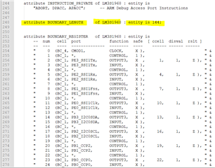
    Right now I'm working on two assumptions. One, I don't have the part in the correct mode to run a correct JTAG test and the other is that the BSDL file has some errors in it.  If it's the BSDL, I'd like to know that the extest file length is actually 144 bits long.  I'd also like to know if the individual register sets are all of the format: Input then Output then Control and that the control should be high in each case.

  • Hi Allan,

    One, I don't have the part in the correct mode to run a correct JTAG test and the other is that the BSDL file has some errors in it.

    I'm not aware a correct mode is required to put into boundary scan test, not just for this device but any IEEE 1149 compliant devices. My understanding is that EXTEST is a mandatory test. See below supported test commands. 

    If it's the BSDL, I'd like to know that the extest file length is actually 144 bits long

      Reading the BSDL file it says it is 144 bits long. 

    I'm using this attached bsdl file. I hope we are using the same file. 

     https://e2e.ti.com/cfs-file/__key/communityserver-discussions-components-files/908/lm3s1968_5F00_ra2_5F00_bga_5F00_v1p0.bsdl

    Can you provide feedback to my earlier questions. Are you seeing the same scan outputs on other LM3S1968 devices?

  • Hi Charles,

    I looked at my test and I'm using the same BDSL file and I'm also using EXTEST.

    I've also been going through the errata for the part and I found some JTAG errors in it.

    I looked at the data code and it looks like it's 0x1C which is 2 months after the errata says it was fixed.  Could this still be a part that has this error?

    The full chip info is: 1BZ0A2SD, $9-1CP56OH.

    The BSDL file says it's for LM3S1968, Revision 2

    I don't know if that applies to my part.

    Here's another JTAG error:

    It concerns INTEST, but I've disable it and I still get the same results.

  • Hi Allan,

      Thanks for brining up the errata. Since I never worked with this device, I never realize there is a errata associated with this device. Can you show your device marking by taking a picture? If your device marking shows that it is earlier than October 2011 then you most likely are affected by this errata. If you are not sure, please take a picture of the device. It will be good if you have other LM3S1968 devices that are much later than Oct-2011 and test them to see if you get correct result. 

      The revision number 2 on BSDL file does not mean silicon revision. 

  • Here is how the part is marked?

    "LM3S1968

    1BZ0A2SD

    $9-1CP56OH"

    It's only 2 months after the Oct-2011 date.

    Is it possible that the die inside is from an earlier lot?

    If you really need a photo, it may take me a little time.

  • Hi Allan,

      No need for the picture. According to your marking below, it is Fury silicon revision A2. You are affected. This silicon is not fixed for LM3JTAG#01 which is another errata affecting INTEST. I suppose if you try another LM3S with a much later date code you will see the same issue. 

    "LM3S1968

    1BZ0A2SD

    $9-1CP56OH"