This thread has been locked.

If you have a related question, please click the "Ask a related question" button in the top right corner. The newly created question will be automatically linked to this question.

TM4C1290NCPDT: HW I2C Clock corrupting

Part Number: TM4C1290NCPDT

Hi everybody.


We met a I2C problem during immunity test with undesired leakage (~100MHz) which coupled to the bus. 
The main issue looks like corruption of one or more clocks in a message (depends at leakage).

The next oscillogram show reading message and holding line by slave. It happens due to missing one clock and slave is waiting another one to set ACK. 
So, this can be fixed using workaround by adding additional clocks to release SDA to normal state.

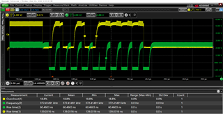
Generally it depends which clock was corrupted, sometimes the slave can detect his address.


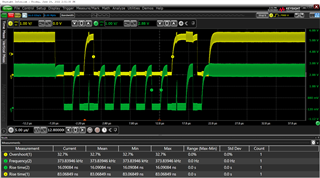
Clock corrupting happens on the MCU side (not a slave), it was verified with MCU standalone.

Used MCU pins: PA6/PA7, HW I2C.
Rise time: ~220nS, Frequency ~400kHz.

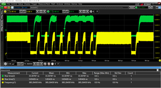
So, we fastly implemented SW I2C by toogling GPIOs configured as Open-Drain and it works fine even with huge leakage comparing with previous one. 


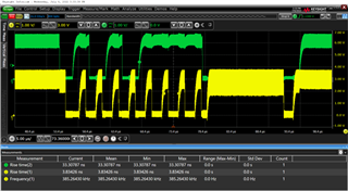
Quick looking of MCU spec and some difference between SDA and SCL was found:
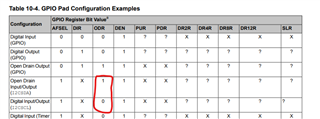


Using debugger, GPIO registers were verified and SCL line is not in the Open Drain State.
So, in the SPMA073 - application report has a more description why we should not do that.


----------------------------------------------------------------------------------------

Do you have any idea why clock can be corrupted like that?  
Could you clarify which electrical difference between described cases (SCL OD behavior by I2C controller / SCL like open drain GPIO), if it exists?

Thanks!

  • Hi,

    We met a I2C problem during immunity test with undesired leakage (~100MHz) which coupled to the bus. 
    The main issue looks like corruption of one or more clocks in a message (depends at leakage).

    I have a couple of questions.

      - What is this immunity test?

     - Are you missing SCL clock only when you are in this immunity test?

     - What happens to SCL if you are conducting immunity test?

     - For experiment, what happens if you run SCL at 100kHz instead of 400kHz? Do you see the same problem when you either apply immunity test or no immunity test?

     - Can you repeat the same problem on another board?

     - Can you do a ABA swap test - meaning to swap another fresh MCU on the existing board. Can you repeat the same problem on the new MCU?

     - Can you repeat the same problem on the LaunchPad?

    Could you clarify which electrical difference between described cases (SCL OD behavior by I2C controller / SCL like open drain GPIO), if it exists?

    The GPIO pins in general can be configured for open-drain. However, the open-drain circuit for the SCL pin is already built in to the I2C module and the open-drain nature of it needs not be handled by the GPIO configuration. 

  • Thanks for your feadback.
    Below you can find my answers:

    What is this immunity test?
    -This is attempt to reproduce control issue in lab from real application.

    -Are you missing SCL clock only when you are in this immunity test?
    We dont have any problem without specific leakage with HW I2C and SW I2C too for 100/400kHz clock. No missing clock and holding the line, everything is fine.

    -what happens if you run SCL at 100kHz instead of 400kHz?

    Running with 100kHz frequency does not solve the missing clocks

    - Can you repeat the same problem on another board?
    Yes,it is the same behavior on another board sample.

     - Can you do a ABA swap test - meaning to swap another fresh MCU on the existing board. Can you repeat the same problem on the new MCU?
    It is possible, but not so fast. 

     - Can you repeat the same problem on the LaunchPad?
    We can try to reproduce it on evb.


    PS. We can fix issue in HW design, but I want to undestand a reason of observed clock behavior when undesired leakage presenses.

  • Hi,

      Thanks for providing the answers to my queries. Please update us on the ABA swap and LaunchPad result. I really don't know why there is a missing clock other than this is only happening in your controlled immunity test. What is your pull up resistance on the bus? What is the capacitance on the bus? Typically the pull up resistor for your bus is chosen depending on the bus capacitance. So higher the bus capacitance, you'll have to use a lower pull-up resistor.

  • So, Pull-up is 4.7kOhm. Its provide 220nS rise time for 400kHz clock (300ns is max value for this frequency)
    We tried to improve rise time by moving pull-up resistor lower and help of it is negligable comparing with implementation of SW I2C where missing clocks were not observed.

  • Hi,

      Honestly, I have no idea what is causing the clock to miss out in the mist of your immunity test. What is the procedure to run the immunity test?

  • We have I2C cables between master and slave and inject 90-120MHz sinewave using wireloop which round the buswires.

  • Thanks for your test description.  I don't know if your test is according to some IEC test spec. Is the test condition realistic to happen in real life? What would be the behavior at different injection frequency other than 90-120Mhz? What type of environment do you subject the MCU to operate? In any case, there is not much I can offer to remedy the the behavior - missing clock in the mist of intentional high frequency noise coupling. 

  • If you look at GPIOPinTypeI2CSCL API, the SCL is configured with 2mA buffer strength. I wonder if it will improve and make no difference if you change to other drive strength like GPIO_STRENGTH_8MA. 

    void
    GPIOPinTypeI2CSCL(uint32_t ui32Port, uint8_t ui8Pins)
    {
    //
    // Check the arguments.
    //
    ASSERT(_GPIOBaseValid(ui32Port));

    //
    // Make the pin(s) be peripheral controlled.
    //
    GPIODirModeSet(ui32Port, ui8Pins, GPIO_DIR_MODE_HW);

    //
    // Set the pad(s) for push-pull operation.
    //
    GPIOPadConfigSet(ui32Port, ui8Pins, GPIO_STRENGTH_2MA, GPIO_PIN_TYPE_STD);
    }

  • We tried to modify GPIOPinTypeI2CSCL function. No effect.
    ---
    Yes, it can be realiastic, depends where you equipment is located and equipment design, which determine isolation and possible leakage vs frequency.
    So, if you are pretty close to HF/UHF high power radio, then HF/UHF isolation may be like critical parameter of a design.
    --
    Injection different frequency provide different leakage amplitude.

    The leakage should be fixed by HW design improving.
    Now, we have only one workaround - its SW I2C.
    And this workaround is confused me because its better than I2C controller realization.


  • Hi Pavel.

      Have you tried different cables between the master and slave such as cables with better noise isolation? Do you have a different design/project with TM4C in it that you can also demonstrate the problem? What I'd like to know is if a different board design makes a difference. You have not told me the result of using the LaunchPad yet. Can you please do that?

      If you are seeing the same problem on any cables and all the boards you have then I really don't have anything to offer here. Sorry for lack of guidance. 

  • Hi,

      I have not heard back from you. I suppose you have resolved the issue or you realize there is not really something I can offer here at the MCU level to mitigate the situation. Perhaps you may consider some shielding on the cable to reduce the effect of injected noises. I will close this thread for now. If you have some update you can just write back to this post and the post will automatically reopen.