Other Parts Discussed in Thread: UNIFLASH,
Greetings,
We've recently received 5 boards from our assembly house. These boards utilize the TMS5700432BPZQQ1 chip and have the same PCB artwork as prior boards, which have worked just fine in the past. The following are the steps that I executed to sanity-check and then produce the error.
- I power-on the boards, and then measure the voltage rails that power the chip; they measure in spec (3.3V and 1.2V).
- I power-off the boards, and then measure the continuity from the MCU leads to the programming header pins; they are continuous.
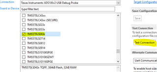
- I power-on the boards, and then plug in the programming header, and then bring up the UniFlash application on my laptop.
- I go through the process of selecting the debugger/programmer as well as the onboard chip.
- I select the desired FW to program, and then I select "Load" to program the chip; I receive an error: Error -2131 @0x0 — Unable to access device register.
This is the same error for all five (5) boards received. Again, this is the same exact PCB artwork of prior boards that we know to not have this problem.

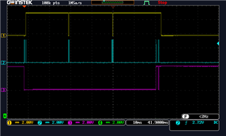
To rule out the programmer being bad, I sought to demonstrate that I could at least program boards that were ordered prior to these 5 "bad boards". The board that I selected was the same exact PCB artwork (same internal part number and revision number; i.e. no difference in the design files). Running through the same exact steps as described prior, I was able to successfully program the board with no issue. I was curious about what the programming signals were supposed to look like, so I scoped the pins and saw the following at the start-up of programming. Obviously there was more activity after start-up, but for comparison sake, I thought this was all that would be necessary to share for reference against for the "bad board", as the "bad board" failed at start-up. Below is a screenshot of the "good board" at the beginning of programming. (Note: CH1: nTRST; CH2: TCK, CH3: TDI, CH4: TDO).

Going back to the "bad board", I did the same as before and scoped some of the programming signals. Jumping ahead to the result, it looks like the TDI line (CH3) was not able to complete what it was trying to do. It also looks like there was absolutely no activity on the TDO line (CH4). Frustrated with this outcome, that I had the Functional Safety version of this chip (RM42L432BPZT) purchased, which has the same package, pin out, and ARM Cortex-R4F architecture — the only difference I could ascertain is the temperature range. I installed the chip as a substitute; same result; I was not able to program it. Below is a screenshot of the "bad board" at the beginning of programming. (Note: CH1: nTRST; CH2: TCK, CH3: TDI, CH4: TDO).
What's more, for kicks, I decided to see what error would result if I did not have any chip soldered to the board. So I de-soldered the MCU from the board and, lo and behold, it was the same error I was getting for these new boards: Error -2131 — Unable to access the device register. as an extra sanity check, with the chip removed, I used a multi-meter to check for continuity between the pads on the MCU footprint and the pins on the programming header. There was continuity as expected. I did the same with another board with the leads of the chip and the pins of the programming header: Continuity was there too. I used a multi-meter to verify that all of the pins were receiving power from the respective power rail: they were.
I am out of ideas.
- What could be going wrong?
- What should I be looking for onboard as a cause?
- Are there batches of bad chips on Digi-Key or Mouser? Is that even a likely possibility?
- Does TI have any samples that they could send us to try in place of these chips?
Please let me know.