Hi
I 'm verify AM243x EPWM function by using demo code epwm_duty_cycle_am243x-lp_r5fss0-0_freertos_ti-arm-clang in SDK8.3
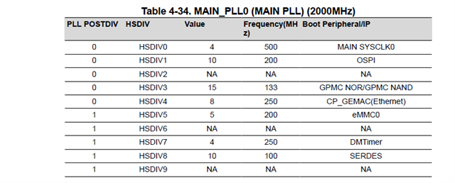
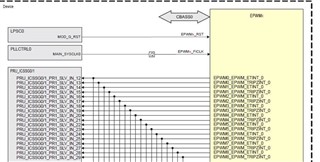
When I look into TRM, it shows the maximum TBCLK = FICLK and FICLK = Main_SYS_CLK0/2 = 400MHz.
However, I found SDK setting FICLK is only set to 250MHZ. I try to generate 100KHz waveform by using FICLK=250Mhz and FICLK=400MHz. I got wrong the waveform (frequency) by using FICLK=400MHz
Please refer to following two pictures:
FICLK=250MHZ
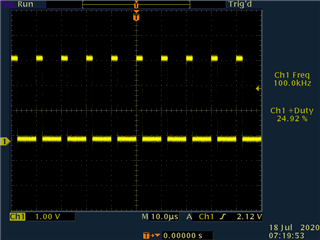
FICLK=400MHz
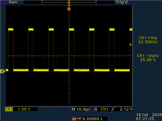
The only change in these two codes is
/* TB frequency in Hz - so that /4 divider is used */
//#define APP_EPWM_TB_FREQ (CONFIG_EPWM0_FCLK / 1U)
#define APP_EPWM_TB_FREQ (400000000)
Please refer to source code
/*
* Copyright (C) 2021 Texas Instruments Incorporated
*
* Redistribution and use in source and binary forms, with or without
* modification, are permitted provided that the following conditions
* are met:
*
* Redistributions of source code must retain the above copyright
* notice, this list of conditions and the following disclaimer.
*
* Redistributions in binary form must reproduce the above copyright
* notice, this list of conditions and the following disclaimer in the
* documentation and/or other materials provided with the
* distribution.
*
* Neither the name of Texas Instruments Incorporated nor the names of
* its contributors may be used to endorse or promote products derived
* from this software without specific prior written permission.
*
* THIS SOFTWARE IS PROVIDED BY THE COPYRIGHT HOLDERS AND CONTRIBUTORS
* "AS IS" AND ANY EXPRESS OR IMPLIED WARRANTIES, INCLUDING, BUT NOT
* LIMITED TO, THE IMPLIED WARRANTIES OF MERCHANTABILITY AND FITNESS FOR
* A PARTICULAR PURPOSE ARE DISCLAIMED. IN NO EVENT SHALL THE COPYRIGHT
* OWNER OR CONTRIBUTORS BE LIABLE FOR ANY DIRECT, INDIRECT, INCIDENTAL,
* SPECIAL, EXEMPLARY, OR CONSEQUENTIAL DAMAGES (INCLUDING, BUT NOT
* LIMITED TO, PROCUREMENT OF SUBSTITUTE GOODS OR SERVICES; LOSS OF USE,
* DATA, OR PROFITS; OR BUSINESS INTERRUPTION) HOWEVER CAUSED AND ON ANY
* THEORY OF LIABILITY, WHETHER IN CONTRACT, STRICT LIABILITY, OR TORT
* (INCLUDING NEGLIGENCE OR OTHERWISE) ARISING IN ANY WAY OUT OF THE USE
* OF THIS SOFTWARE, EVEN IF ADVISED OF THE POSSIBILITY OF SUCH DAMAGE.
*/
#include <kernel/dpl/DebugP.h>
#include <kernel/dpl/AddrTranslateP.h>
#include <kernel/dpl/SemaphoreP.h>
#include <kernel/dpl/HwiP.h>
#include <drivers/epwm.h>
#include "ti_drivers_config.h"
#include "ti_drivers_open_close.h"
#include "ti_board_open_close.h"
/*
* This example uses the ePWM module to generate a signal for a specified time
* and with a specified duty cycle.
*
* The default parameters are : Frequency : 1kHz, Duty cycle : 25%,
* App run time : 60s (time for which signal is generated). All these parameters
* are configurable.
*
* In this example ePWM0 is used to generate the signal, the user can also
* select a different one.
*
* This example also showcases how to configure and use the ePWM module.
*/
/* Output channel - A or B */
#define APP_EPWM_OUTPUT_CH (EPWM_OUTPUT_CH_A)
/* Duty Cycle of PWM output signal in % - give value from 0 to 100 */
#define APP_EPWM_DUTY_CYCLE (25U)
/* Frequency of PWM output signal in Hz - 1 KHz is selected */
#define APP_EPWM_OUTPUT_FREQ (100U*1000U)
/* APP run time in seconds */
#define APP_EPWM_RUN_TIME (60U)
/* TB frequency in Hz - so that /4 divider is used */
//#define APP_EPWM_TB_FREQ (CONFIG_EPWM0_FCLK / 1U)
#define APP_EPWM_TB_FREQ (400000000)
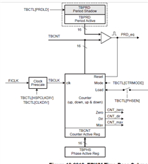
/*
* PRD value - this determines the period
* PRD = (TBCLK/PWM FREQ) / 2
* /2 is added becasue up&down counter is selected. So period is 2 times
*/
#define APP_EPWM_PRD_VAL ((APP_EPWM_TB_FREQ / APP_EPWM_OUTPUT_FREQ) / 2U)
/*
* COMPA value - this determines the duty cycle
* COMPA = (PRD - ((dutycycle * PRD) / 100)
*/
#define APP_EPWM_COMPA_VAL (APP_EPWM_PRD_VAL - ((APP_EPWM_DUTY_CYCLE * \
APP_EPWM_PRD_VAL) / 100U))
/* Global variables and objects */
static HwiP_Object gEpwmHwiObject;
static SemaphoreP_Object gEpwmSyncSemObject;
/* Function Prototypes */
static void App_epwmIntrISR(void *handle);
static void App_epwmConfig(uint32_t epwmBaseAddr,
uint32_t epwmCh,
uint32_t epwmFuncClk);
/* variable to hold base address of EPWM that is used */
uint32_t gEpwmBaseAddr;
void epwm_duty_cycle_main(void *args)
{
int32_t status;
uint32_t numIsrCnt = (APP_EPWM_RUN_TIME * APP_EPWM_OUTPUT_FREQ);
HwiP_Params hwiPrms;
/* Open drivers to open the UART driver for console */
Drivers_open();
Board_driversOpen();
DebugP_log("EPWM Duty Cycle Test Started ...\r\n");
DebugP_log("Please refer EXAMPLES_DRIVERS_EPWM_DUTY_CYCLE example user \
guide for the test setup to probe EPWM signal. \r\n");
DebugP_log("App will wait for 60 seconds (using PWM period ISR) ...\r\n");
/* Address translate */
gEpwmBaseAddr = (uint32_t)AddrTranslateP_getLocalAddr(CONFIG_EPWM0_BASE_ADDR);
status = SemaphoreP_constructCounting(&gEpwmSyncSemObject, 0, numIsrCnt);
DebugP_assert(SystemP_SUCCESS == status);
/* Register & enable interrupt */
HwiP_Params_init(&hwiPrms);
hwiPrms.intNum = CONFIG_EPWM0_INTR;
hwiPrms.callback = &App_epwmIntrISR;
hwiPrms.isPulse = CONFIG_EPWM0_INTR_IS_PULSE;
status = HwiP_construct(&gEpwmHwiObject, &hwiPrms);
DebugP_assert(status == SystemP_SUCCESS);
/* Configure PWM */
App_epwmConfig(gEpwmBaseAddr, APP_EPWM_OUTPUT_CH, CONFIG_EPWM0_FCLK);
while(numIsrCnt > 0)
{
SemaphoreP_pend(&gEpwmSyncSemObject, SystemP_WAIT_FOREVER);
numIsrCnt--;
}
while(1);
EPWM_etIntrDisable(gEpwmBaseAddr);
EPWM_etIntrClear(gEpwmBaseAddr); /* Clear any pending interrupts if any */
HwiP_destruct(&gEpwmHwiObject);
SemaphoreP_destruct(&gEpwmSyncSemObject);
DebugP_log("EPWM Duty Cycle Test Passed!!\r\n");
DebugP_log("All tests have passed!!\r\n");
Board_driversClose();
Drivers_close();
}
static void App_epwmIntrISR(void *handle)
{
volatile uint16_t status;
status = EPWM_etIntrStatus(gEpwmBaseAddr);
if(status & EPWM_ETFLG_INT_MASK)
{
SemaphoreP_post(&gEpwmSyncSemObject);
EPWM_etIntrClear(gEpwmBaseAddr);
}
return;
}
static void App_epwmConfig(uint32_t epwmBaseAddr,
uint32_t epwmCh,
uint32_t epwmFuncClk)
{
EPWM_AqActionCfg aqConfig;
/* Configure Time base submodule */
EPWM_tbTimebaseClkCfg(epwmBaseAddr, APP_EPWM_TB_FREQ, epwmFuncClk);
EPWM_tbPwmFreqCfg(epwmBaseAddr, APP_EPWM_TB_FREQ, APP_EPWM_OUTPUT_FREQ,
EPWM_TB_COUNTER_DIR_UP_DOWN,
EPWM_SHADOW_REG_CTRL_ENABLE);
EPWM_tbSyncDisable(epwmBaseAddr);
EPWM_tbSetSyncOutMode(epwmBaseAddr, EPWM_TB_SYNC_OUT_EVT_SYNCIN);
EPWM_tbSetEmulationMode(epwmBaseAddr, EPWM_TB_EMU_MODE_FREE_RUN);
/* Configure counter compare submodule */
EPWM_counterComparatorCfg(epwmBaseAddr, EPWM_CC_CMP_A,
APP_EPWM_COMPA_VAL, EPWM_SHADOW_REG_CTRL_ENABLE,
EPWM_CC_CMP_LOAD_MODE_CNT_EQ_ZERO, TRUE);
EPWM_counterComparatorCfg(epwmBaseAddr, EPWM_CC_CMP_B,
APP_EPWM_COMPA_VAL, EPWM_SHADOW_REG_CTRL_ENABLE,
EPWM_CC_CMP_LOAD_MODE_CNT_EQ_ZERO, TRUE);
/* Configure Action Qualifier Submodule */
aqConfig.zeroAction = EPWM_AQ_ACTION_DONOTHING;
aqConfig.prdAction = EPWM_AQ_ACTION_DONOTHING;
aqConfig.cmpAUpAction = EPWM_AQ_ACTION_HIGH;
aqConfig.cmpADownAction = EPWM_AQ_ACTION_LOW;
aqConfig.cmpBUpAction = EPWM_AQ_ACTION_HIGH;
aqConfig.cmpBDownAction = EPWM_AQ_ACTION_LOW;
EPWM_aqActionOnOutputCfg(epwmBaseAddr, epwmCh, &aqConfig);
/* Configure Dead Band Submodule */
EPWM_deadbandBypass(epwmBaseAddr);
/* Configure Chopper Submodule */
EPWM_chopperEnable(epwmBaseAddr, FALSE);
/* Configure trip zone Submodule */
EPWM_tzTripEventDisable(epwmBaseAddr, EPWM_TZ_EVENT_ONE_SHOT, 0U);
EPWM_tzTripEventDisable(epwmBaseAddr, EPWM_TZ_EVENT_CYCLE_BY_CYCLE, 0U);
/* Configure event trigger Submodule */
EPWM_etIntrCfg(epwmBaseAddr, EPWM_ET_INTR_EVT_CNT_EQ_ZRO,
EPWM_ET_INTR_PERIOD_FIRST_EVT);
EPWM_etIntrEnable(epwmBaseAddr);
}
I would like to get confirm what is the maximum value of FICLK? or any limitation is EPWM resolution?
Regards
Andre