This thread has been locked.

If you have a related question, please click the "Ask a related question" button in the top right corner. The newly created question will be automatically linked to this question.

TM4C1294NCPDT: The reason which the oscillator doesn't move

Part Number: TM4C1294NCPDT

I mount 'TM4C1294NCPDTT3' on the board, but the oscillator doesn't move.

Could you tell me the reason?

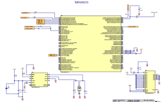
By the way, I wired like the below.
(i) 3.3 V power(without resistor)
Pin number:7, 16, 26, 28, 39, 39, 47, 51, 52, 69, 79, 90, 101, 113, 122, 8

(ii) 3.3 V power(via resistor)
・70 (via 10 kΩ resistor)
・9 (via 1 kΩ resistor)
・68 (via 51Ω resistor)
・60,61 (via 1 kΩ resistor)

(iii) GND(Without resistor)
Pin number:17, 48, 55, 58, 80, 114, 10, 66

(iv) GND(via resistor)
・59 (via 4.7 kΩ)
・62,63 (via 1 kΩ)

(vi)oscillator peripheral
・88 (8 pF and 16 MHz crystal)
・89 (8 pF and 16 MHz crystal)

  • Hello Kanematu-san,

    Can you describe the state of the system in terms of power up and what software has been executed?

    What are the system clock settings you are trying to set for the device?

    Also your description is omitting capacitors. What capacitors do you have on the voltage lines?

    Best Regards,

    Ralph Jacobi

  • Hello, Thank you for your replying.

    (i) >Can you describe the state of the system in terms of power up

    What is state of system?
    I don't confirm it.
    Please tell me what kind of the state of
    system?

    (ii) >what software has been executed?

    What SW are there in TM4C1294NCPDTT3?
    Please tell me kind of them.

    Do we have to write the SW to TM4C194NCPDTT3 before We mount on the board?

    (iii) >What are the system clock settings you are trying to set for the device?

    I want to use Main Oscillator.
    But I don't know the role of it.
    Please tell me about the detail.

    (iv) What capacitors do you have on the voltage lines?

    ・9 Pin
    I connect 0.1 µF and 0.01 µF capacitors in parallel to GND.

    ・68 Pin
    Connect 0.1 µF to GND.

    Basically, I refered to like a below figure

  • Hello Kanematu-san,

    (i) >Can you describe the state of the system in terms of power up

    What is state of system?
    I don't confirm it.
    Please tell me what kind of the state of
    system?

    I am looking for what voltages have been applied to the device, if any code has been loaded and is executing, just something to understand what kind of the state the device might be in like 'power applied to all voltage pins, flash memory blank' or 'power applied, code was executing, and then stopped and oscillator is not moving now'. That said, your description for my last question has given me what I need. This explanation is just for the future.

    What SW are there in TM4C1294NCPDTT3?
    Please tell me kind of them.

    Do we have to write the SW to TM4C194NCPDTT3 before We mount on the board?

    No, there is a ROM boot loader which will execute first. If there is no firmware loaded, then I can assume the ROM boot loader is executing code which is fine - it just lets me understand what the device is supposed to be doing. As above, this explanation is just for the future.

    (iii) >What are the system clock settings you are trying to set for the device?

    I want to use Main Oscillator.
    But I don't know the role of it.
    Please tell me about the detail.

    This question was to understand if you had code loaded and were executing the SysCtlClockFreqSet API to configure the system clock.

    (iv) What capacitors do you have on the voltage lines?

    ・9 Pin
    I connect 0.1 µF and 0.01 µF capacitors in parallel to GND.

    ・68 Pin
    Connect 0.1 µF to GND.

    If that is the extent of the capacitors on the board, you have a lot of missing components. The most critical aspect here and at minimum a cause for the oscillator not working is that all TM4C microcontrollers have an on-chip voltage regulator which provides power to the core and that regulator requires filter capacitors to operate properly.

    Without those filter caps, the core will not be powered and the MCU will not function which explains why the oscillator isn't moving.

    The required capacitance is 3.3uF to 3.4uF. This requires two or more capacitors that total such capacitance - a bulk cap, and a decoupling cap. The two most common chooses are: one each of 3.3μF and 0.1μF capacitors or one each 2.2μF, 1.0μF and 0.1μF.

    Beyond that, the voltage lines should also have bulk and decoupling capacitors on them. The full details of this can be read in our System Design Guidelines document: https://www.ti.com/lit/pdf/spma056

    Section 3.4 cover power in detail and I would recommend a thorough review of that section to address all the missing components on the power lines.

    Best Regards,

    Ralph Jacobi

  • Hello, Thank you for your replying.

    >You said about state of system and SW
    You want to know for the future.
    As a result, you judged you don't have to understand now, don't
    you?

    >You said
    This question was to understand if you had code loaded and were executing the SysCtlClockFreqSet API to configure the system clock.

    I don't execute the SysCtlClockFreqSet API.
    If I don't execute the API, Couldn't the Oscillator move?

    >You said
    Sorry, I can't confirm immediately.
    At the after day, I want to tell the detail power line.

  • Hello Hiroyuki,

    The required capacitance is 3.3uF to 3.4uF. This requires two or more capacitors that total such capacitance - a bulk cap, and a decoupling cap. The two most common chooses are: one each of 3.3μF and 0.1μF capacitors or one each 2.2μF, 1.0μF and 0.1μF.

    Must have PCB trace connects Pins 115 to 87 with capacitor/s shown above, otherwise no good condition to start default PIOSC clock. MCU default oscillator internal PIOSC clock.  Future XDC110 flash CCS project your custom firmware configures MOSC for 16MHz XTAL, Ralf mentions. You must add 0.1uf each side of MCU package, VDD and GND pins each side 4x 0.1uf minimum.

    MCU will run from PIOSC clock without 16MHz XTAL being installed on PCB. 

  • Hello Kanematu-san,

    >You said
    This question was to understand if you had code loaded and were executing the SysCtlClockFreqSet API to configure the system clock.

    I don't execute the SysCtlClockFreqSet API.
    If I don't execute the API, Couldn't the Oscillator move?

    If its a 25MHz oscillator and the ROM boot loader is executing due to no code being in Flash memory (or triggered by application), then it will configure the crystal. Otherwise the external crystal wouldn't be used by the CPU as it would be running from the internal 16MHz oscillator by default.

    So after the capacitance issue is resolved, the next step to get the oscillator moving unless it is 25MHz would be to load a problem that calls the SysCtlClockFreqSet API to configure the external oscillator. TivaWare examples show how to do this, but feel free to verify the API call you intend to use because an incorrect SysCtlClockFreqSet API call can lock the device and which would require JTAG access to unlock (though I think you have that).

    Best Regards,

    Ralph Jacobi