Other Parts Discussed in Thread: SYSCONFIG, TMDSHSECDOCK
Hi,
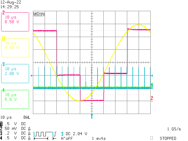
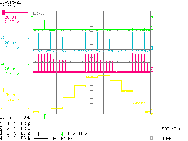
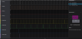
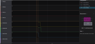
for the ADC's I must use three different sampling frequencies named fs1 (200KHz) , fs2(50KHz) and fs3(1KHz). The frequencies must have a fixed phase relation to each other in order to make sure I do get equidistand sampling all the time for all the SOC's I do configure an all the ADC's I use. In the scope shot below is taken from the control card. I use ePWM0 in this example to create two Triggers for the ADC's SOCA-Trigger and SOCB-Trigger. The source is the very same ePWMx. However for the SOCB-Trigger I divide the number of triggers by four to get fs2 equal 50 KHz.
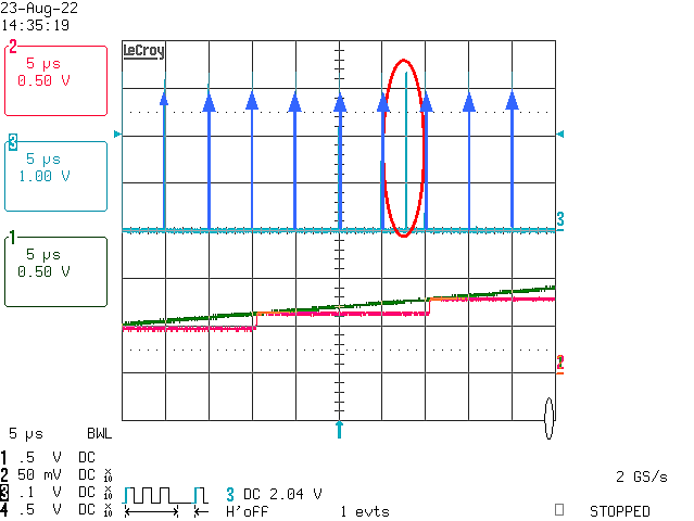
Q: How can I make fs3 (1KHz) by combining another ePWM unit for example ePWM1? I tried to synchronize ePWM0 with ePWM1. However no luck so far. Also it is difficult to verify, since at the moment on the control card I only can probe GPIO-Pin-R3. On the scope shot fs1 is shown in blue.
The legend on the scope shot is the following:
- Channel 1 (Yellow) is a 10 KHz sine wave from a function generator
- Channel 2 (Magenta) is the DAC output on the control card feeded (per DMA channel) by samples taken on ADC0 channel 0 every fs2 (50KHz)
- Channel 3 (Blue) is SOCA-Trigger brought out to pin R3 on the control card.
As we can see and as we expect the two triggers (fs1 & fs2) are phase aligned. Now a good idea and a little help is need to get fs3 phase aligned as well. Any help would be appreciated.
Markus