This thread has been locked.

If you have a related question, please click the "Ask a related question" button in the top right corner. The newly created question will be automatically linked to this question.

EK-TM4C123GXL: I2C SCL Line Remaining Low?

Part Number: EK-TM4C123GXL
Other Parts Discussed in Thread: TMP117

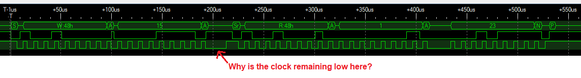
I'm using a Tiva Dev Board (TM4C123G) to read I2C from this AdaFruit temperature sensor.  I'm reading a 2 byte value from register 0x0F of the temperature sensor.  It works, the expected value is what I'm receiving (0x0117) but I'm wondering why the SCL line remains low after doing the first write where I write the address of the temperature sensor.  Here's what I've captured with a logic analyzer:

The code I'm using seems correct and is fairly straightforward as far as writing the register and then reading the two bytes:

    // Set up the slave address with write transaction
    MAP_I2CMasterSlaveAddrSet(i2cChannelInfo[channel].i2cBase, slaveAddress, false);
    WAIT_ON_I2C_BUS_BUSY(channel);

    // Store the command data in I2C data register
    MAP_I2CMasterDataPut(i2cChannelInfo[channel].i2cBase, registerAddress);
    WAIT_ON_I2C_BUS_BUSY(channel);

    // Start the I2C transaction
    MAP_I2CMasterControl(i2cChannelInfo[channel].i2cBase, I2C_MASTER_CMD_BURST_SEND_START);
    WAIT_ON_I2C_BUS_BUSY(channel);

    // Set the data direction to true since the I2C Master is initiating a read from the slave
    MAP_I2CMasterSlaveAddrSet(i2cChannelInfo[channel].i2cBase, slaveAddress, true);
    WAIT_ON_I2C_BUS_BUSY(channel);

    // Start receiving data in burst mode
    MAP_I2CMasterControl(i2cChannelInfo[channel].i2cBase, I2C_MASTER_CMD_BURST_RECEIVE_START);
    WAIT_ON_I2C_BUS_BUSY(channel);

    // Get the first byte
    *outputWord = (MAP_I2CMasterDataGet(i2cChannelInfo[channel].i2cBase) & 0xFF) << (byteOrder == I2C_LSB_FIRST ? 0 : 8);
    WAIT_ON_I2C_BUS_BUSY(channel);

    // Request the second (and final) byte
    MAP_I2CMasterControl(i2cChannelInfo[channel].i2cBase, I2C_MASTER_CMD_BURST_RECEIVE_FINISH);
    WAIT_ON_I2C_BUS_BUSY(channel);

    // Read the second byte of data
    *outputWord |= (MAP_I2CMasterDataGet(i2cChannelInfo[channel].i2cBase) & 0xFF) << (byteOrder == I2C_LSB_FIRST ? 8 : 0);
    WAIT_ON_I2C_BUS_BUSY(channel);

The macro WAIT_ON_I2C_BUS_BUSY macro is defined as:

#define WAIT_ON_I2C_BUS_BUSY(CHANNEL) if(I2CWaitOnMasterBusy(CHANNEL) == false) { EndCriticalSection(); return false; }

Anyone have any thoughts?

  • Hello Terence,

    I would guess it's because you used I2C_MASTER_CMD_BURST_SEND_START but only send one byte.

    For this use case, I would recommend you just use I2C_MASTER_CMD_SINGLE_SEND to send a single byte.

    Best Regards,

    Ralph Jacobi

  • Hi Ralph - Thanks for the quick reply.  Actually, I was originally using I2C_MASTER_CMD_SINGLE_SEND instead of  I2C_MASTER_CMD_BURST_SEND_START but I noticed when using I2C_MASTER_CMD_SINGLE_SEND it was showing a "stop" after the write and I was concerned that would confuse the slave since I still needed to do the read from the register.

    Here is the transaction when using I2C_MASTER_CMD_SINGLE_SEND:

    Here's the code.  All I did was change the I2C_MASTER_CMD_BURST_SEND_START to a I2C_MASTER_CMD_SINGLE_SEND:

        // Make sure the bus isn't busy before trying to start the transaction
        WAIT_ON_I2C_BUS_BUSY(channel);
    
        // Set up the slave address with write transaction
        MAP_I2CMasterSlaveAddrSet(i2cChannelInfo[channel].i2cBase, slaveAddress, false);
        WAIT_ON_I2C_BUS_BUSY(channel);
    
        // Store the command data in I2C data register
        MAP_I2CMasterDataPut(i2cChannelInfo[channel].i2cBase, registerAddress);
        WAIT_ON_I2C_BUS_BUSY(channel);
    
        // Start the I2C transaction
        MAP_I2CMasterControl(i2cChannelInfo[channel].i2cBase, I2C_MASTER_CMD_SINGLE_SEND);
        WAIT_ON_I2C_BUS_BUSY(channel);
    
        // Set the data direction to true since the I2C Master is initiating a read from the slave
        MAP_I2CMasterSlaveAddrSet(i2cChannelInfo[channel].i2cBase, slaveAddress, true);
        WAIT_ON_I2C_BUS_BUSY(channel);
    
        // Start receiving data in burst mode
        MAP_I2CMasterControl(i2cChannelInfo[channel].i2cBase, I2C_MASTER_CMD_BURST_RECEIVE_START);
        WAIT_ON_I2C_BUS_BUSY(channel);
    
        // Get the first byte
        *outputWord = (MAP_I2CMasterDataGet(i2cChannelInfo[channel].i2cBase) & 0xFF) << (byteOrder == I2C_LSB_FIRST ? 0 : 8);
        WAIT_ON_I2C_BUS_BUSY(channel);
    
        // Request the second (and final) byte
        MAP_I2CMasterControl(i2cChannelInfo[channel].i2cBase, I2C_MASTER_CMD_BURST_RECEIVE_FINISH);
        WAIT_ON_I2C_BUS_BUSY(channel);
    
        // Read the second byte of data
        *outputWord |= (MAP_I2CMasterDataGet(i2cChannelInfo[channel].i2cBase) & 0xFF) << (byteOrder == I2C_LSB_FIRST ? 8 : 0);
        WAIT_ON_I2C_BUS_BUSY(channel);

    Also, I found this DigiKey tutorial on doing I2C communication with the Tiva and it used a I2C_MASTER_CMD_BURST_SEND_START to send a single register register to the slave device when doing an I2C read.  See the section titled "I2C Receive Function".

    Unfortunately there are no multiple byte read examples in the TivaWare Peripheral Lib document (SW-TM4C-DRL-UG-2.1.3.156) or example code. 

  • Hello Terence,

    So my typical experience with I2C devices has been that the correct usage is to use I2C_MASTER_CMD_SINGLE_SEND and which generates that STOP condition before the data read is done. That said, I was looking through the datasheet of the TMP117 and I can see the cause for concern with taking this approach given how the communication is outlined. The only STOP condition should be issued at the end of the transfer.

    The process of using a single send versus burst style commands really is set to dictate when START and STOP conditions are sent, so the way you've written the code would match the TMP117 datasheet in terms of when START and STOP conditions would be sent.

    That leaves the question of why the SCL line is low during that period of time. It isn't being controlled by the TMP117 as the datasheet explicitly states the device will not drive the SCL line so its the TM4C that is holding it low.

    My guess then is that the SCL line is being held low as the peripheral waits for clarity on what to do next. If it needs to issue a STOP condition, the SCL needs to be kept low from the last clock. So the state machine is keeping it low in anticipation of that until it received instruction regarding what next step should occur. I don't see any fundamental issue with that as the communication is on going at that time, and you have confirmed it is working fine.

    Regarding multiple bye read examples, we did have a gap regarding that but in TivaWare 2.2.0 we released a new simplified I2C example that covers this sort of use case. However the sensor in question worked fundamentally different in that the Master triggered a reading and then read the result after a delay. Here are the APIs we used for your reference:

    //*****************************************************************************
    //
    // This function sends the specified command to the I2C slave device.
    //
    //*****************************************************************************
    void
    I2CWriteCommand(uint32_t ui32Command)
    {
        //
        // Set up the slave address with write transaction.
        //
        MAP_I2CMasterSlaveAddrSet(I2C3_BASE, SHT21_I2C_ADDRESS, false);
    
        //
        // Store the command data in I2C data register.
        //
        MAP_I2CMasterDataPut(I2C3_BASE, ui32Command);
    
        //
        // Start the I2C transaction.
        //
        MAP_I2CMasterControl(I2C3_BASE, I2C_MASTER_CMD_SINGLE_SEND);
    
        //
        // Wait until the I2C transaction is complete.
        //
        while(MAP_I2CMasterBusy(I2C3_BASE))
        {
        }
    }

    //*****************************************************************************
    //
    // This function will read three 8-bit data from the I2C slave.  The first
    // two 8-bit data forms the humidity data while the last 8-bit data is the
    // checksum. This function illustrates three different I2C burst mode
    // commands to read the I2C slave device.
    //
    //*****************************************************************************
    void
    I2CReadCommand(uint32_t * pui32DataRx)
    {
        //
        // Modify the data direction to true, so that seeing the address will
        // indicate that the I2C Master is initiating a read from the slave.
        //
        MAP_I2CMasterSlaveAddrSet(I2C3_BASE, SHT21_I2C_ADDRESS, true);
    
        //
        // Setup for first read.  Use I2C_MASTER_CMD_BURST_RECEIVE_START
        // to start a burst mode read.  The I2C master continues to own
        // the bus at the end of this transaction.
        //
        MAP_I2CMasterControl(I2C3_BASE, I2C_MASTER_CMD_BURST_RECEIVE_START);
    
        //
        // Wait until master module is done transferring.
        //
        while(MAP_I2CMasterBusy(I2C3_BASE))
        {
        }
    
        //
        // Read the first byte data from the slave.
        //
        pui32DataRx[0] = MAP_I2CMasterDataGet(I2C3_BASE);
    
        //
        // Setup for the second read.  Use I2C_MASTER_CMD_BURST_RECEIVE_CONT
        // to continue the burst mode read.  The I2C master continues to own
        // the bus at the end of this transaction.
        //
        MAP_I2CMasterControl(I2C3_BASE, I2C_MASTER_CMD_BURST_RECEIVE_CONT);
    
        //
        // Wait until master module is done transferring.
        //
        while(MAP_I2CMasterBusy(I2C3_BASE))
        {
        }
    
        //
        // Read the second byte data from the slave.
        //
        pui32DataRx[1] = MAP_I2CMasterDataGet(I2C3_BASE);
    
        //
        // Setup for the third read.  Use I2C_MASTER_CMD_BURST_RECEIVE_FINISH
        // to terminate the I2C transaction.  At the end of this transaction,
        // the STOP bit will be issued and the I2C bus is returned to the
        // Idle state.
        //
        MAP_I2CMasterControl(I2C3_BASE, I2C_MASTER_CMD_BURST_RECEIVE_FINISH);
    
        //
        // Wait until master module is done transferring.
        //
        while(MAP_I2CMasterBusy(I2C3_BASE))
        {
        }
        
        //
        // Note the third 8-bit data is the checksum byte.  It will be
        // left to the users as an exercise if they want to verify if the
        // checksum is correct.
        pui32DataRx[2] = MAP_I2CMasterDataGet(I2C3_BASE);
    }

    And this is the application code used:

            //
            // Write the command to start a humidity measurement.
            //
            I2CWriteCommand(TRIGGER_RH_MEASUREMENT);
    
            //
            // Per SHT21 sensor datasheet, the humidity measurement
            // can take a maximum of 29ms to complete at 12-bit
            // resolution.  Here we will wait for 33ms.
            //
            MAP_SysCtlDelay(MAP_SysCtlClockGet() / (30 * 3));
    
            //
            // Read the humidity measurements.
            //
            I2CReadCommand(&pui32DataRx[0]);

    Hope all of this information clarifies what you are seeing and confirms that you are using the appropriate APIs for the particular sensor in question.

    Best Regards,

    Ralph Jacobi

  • Thank you for the thorough response.  Much appreciated.