This thread has been locked.

If you have a related question, please click the "Ask a related question" button in the top right corner. The newly created question will be automatically linked to this question.

RM57L843: [Custom board] DAP access error when debugging

Part Number: RM57L843
Other Parts Discussed in Thread: HALCOGEN

Hello Team,

I'm posting on behalf of my customer. Please see inquiry below:

 I'm getting errors when attempting to debug a custom board with the RM57 using the XDS110 debug probe.

 Details:

- Testing using Hello World program

- JTAG test connection is successful

- If a release build is loaded then the MCU can be programmed with another build with no errors

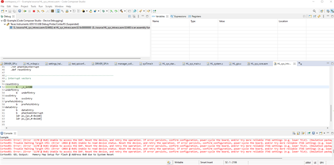
- If a debug build is loaded and  I attempt to load a program then I get this error:  

"[ERROR] Dap: Error connecting to the target: (Error -1170 @ 0x0) Unable to access the DAP. Reset the device, and retry the operation. If error persists, confirm configuration, power-cycle the board, and/or try more reliable JTAG settings (e.g. lower TCLK). (Emulation package 9.7.0.00213)".

After pressing the Warm Reset the warm reset button at the right time, the log shows:

"CortexR5: GEL Output: Memory Map Setup for Flash @ Address 0x0CortexR5: GEL Output: Memory Map Setup for Flash @ Address 0x0 due to System Reset"

- Then if I hit resume in the debugger, this starts repeating:

"CortexR5: Error: (Error -1170 @ 0x0) Unable to access the DAP. Reset the device, and retry the operation. If error persists, confirm configuration, power-cycle the board, and/or try more reliable JTAG settings (e.g. lower TCLK). (Emulation package 9.6.0.00172) 

CortexR5: Trouble Halting Target CPU: (Error -2064 @ 0x0) Unable to read device status. Reset the device, and retry the operation. If error persists, confirm configuration, power-cycle the board, and/or try more reliable JTAG settings (e.g. lower TCLK). (Emulation package 9.6.0.00172) "
 
However, the XDS110 has access the the warm reset pin and I can see on the oscilloscope that it isn't attempting to reset the device. I can also hit reset during this and it'll go back to:
"CortexR5: GEL Output: Memory Map Setup for Flash @ Address 0x0 due to System Reset"

 Additional troubleshooting steps:

- I looked at this webpage: https://software-dl.ti.com/ccs/esd/documents/ccs_debugging_jtag_connectivity_issues.html but the link for "A procedure to try and unlock a Hercules device is described in this e2e forum thread." gives the error that the page is not found.

 - I checked my voltage supervisors and they do not appear to be triggering a power reset

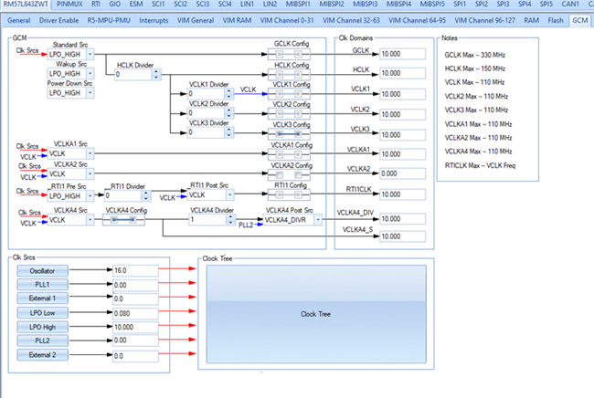
- Reduced the JTAG clock speed to the minimum (100 kHz)

 - Launch target configuration appears to connect successfully then when I hit run, it repeats errors -2064 and -1170

 I'm not sure if there's some initial unlocking procedure to be done with new chips to get them in debug mode (I know this is true for other MCUs but I didn't find it for Hercules).  Are there initial programming instructions for new chips? I don't think it's a power issue as the voltage supervisors aren't triggering and the JTAG test is successful. If it is a hardware error, then what could it be?

 JTAG Test Connection Log:

[Start: Texas Instruments XDS110 USB Debug Probe]

Execute the command:

%ccs_base%/common/uscif/dbgjtag -f %boarddatafile% -rv -o -S integrity

[Result]

-----[Print the board config pathname(s)]------------------------------------

C:\Users\Lesley\AppData\Local\TEXASI~1\CCS\
    ccs1110\0\0\BrdDat\testBoard.dat

-----[Print the reset-command software log-file]-----------------------------

This utility has selected a 100- or 510-class product.
This utility will load the adapter 'jioxds110.dll'.
The library build date was 'Dec  8 2021'.
The library build time was '11:16:32'.
The library package version is '9.6.0.00172'.
The library component version is '35.35.0.0'.
The controller does not use a programmable FPGA.
The controller has a version number of '5' (0x00000005).
The controller has an insertion length of '0' (0x00000000).
This utility will attempt to reset the controller.
This utility has successfully reset the controller.

-----[Print the reset-command hardware log-file]-----------------------------

The scan-path will be reset by toggling the JTAG TRST signal.
The controller is the XDS110 with USB interface.
The link from controller to target is direct (without cable).
The software is configured for XDS110 features.
The controller cannot monitor the value on the EMU[0] pin.
The controller cannot monitor the value on the EMU[1] pin.
The controller cannot control the timing on output pins.
The controller cannot control the timing on input pins.
The scan-path link-delay has been set to exactly '0' (0x0000).

-----[Perform the Integrity scan-test on the JTAG IR]------------------------

This test will use blocks of 64 32-bit words.
This test will be applied just once.

Do a test using 0xFFFFFFFF.
Scan tests: 1, skipped: 0, failed: 0
Do a test using 0x00000000.
Scan tests: 2, skipped: 0, failed: 0
Do a test using 0xFE03E0E2.
Scan tests: 3, skipped: 0, failed: 0
Do a test using 0x01FC1F1D.
Scan tests: 4, skipped: 0, failed: 0
Do a test using 0x5533CCAA.
Scan tests: 5, skipped: 0, failed: 0
Do a test using 0xAACC3355.
Scan tests: 6, skipped: 0, failed: 0
All of the values were scanned correctly.

The JTAG IR Integrity scan-test has succeeded.

-----[Perform the Integrity scan-test on the JTAG DR]------------------------

This test will use blocks of 64 32-bit words.
This test will be applied just once.

Do a test using 0xFFFFFFFF.
Scan tests: 1, skipped: 0, failed: 0
Do a test using 0x00000000.
Scan tests: 2, skipped: 0, failed: 0
Do a test using 0xFE03E0E2.
Scan tests: 3, skipped: 0, failed: 0
Do a test using 0x01FC1F1D.
Scan tests: 4, skipped: 0, failed: 0
Do a test using 0x5533CCAA.
Scan tests: 5, skipped: 0, failed: 0
Do a test using 0xAACC3355.
Scan tests: 6, skipped: 0, failed: 0
All of the values were scanned correctly.

The JTAG DR Integrity scan-test has succeeded.

[End: Texas Instruments XDS110 USB Debug Probe]

Regards,

Renan

  • Hi Runan,

    Can you please take a look at the routing of the JTAG signals? If the total signal length from the scan controller to the MCU is long (>6") and not properly terminated, reflections on TCK or RTCK can cause some problem.  The crosstalk from TDI, TMS or TDO onto TCK or RTCK can have the same effect.

  • Hello Qj,

    Good day. Please see my customer response below:

    The JTAG trace lengths on the board are 1.6-3 in so with the 4 in debug cable they would be over 6 in but I can’t probe the signals with that setup. With my debug setup with the breadboard, this is now about 14 inches in total length (xds110 - wire - probe - wire - board - MCU) so I switched to 100kHz JTAG TCLK frequency. This is the setup for the oscilloscope.

     I’m using a 10-pin connector. TMS has a 10k pullup. TCK has a 10k pullup and a 100 resistor with 22pF capacitor connected to ground. TDO has a 22 ohm termination resistor. RTCK is not connected. nTRST and nRST (this is pulled up and wired to a pushbutton) are connected.

     I see a bit of distortion on TDO but it doesn’t seem very large, see pictures below. I assumed the test connection would fail if there was significant reflection. For the following: yellow – TMS, green – TDI, blue – TDO and red – TCK.

    6332.image.zip

    Regards,

    Renan

  • nTRST and nRST (this is pulled up and wired to a pushbutton) are connected.

    If you have a pull-up on nTRST, please remove the pull-up resistor. If possible, please pull-down the nTRST on your board? 

    The signal waveforms look fine to me. 

  • Hello QJ,

    Good day. Please see my customer response below:

    nTRST in the design/debug setup currently has no pullup or pulldown externally. From my understanding of the datasheet, the MCU has an internal pulldown. Does it need a 10k pulldown? I can add one to the breakout board but the signal appears to be low by default according to the oscilloscope.

    Regards,

    Renan

  • Hi Renan,

    You can use the internal pull-down for nTRST. The project modes (release or debug) should not affect the target connection and image loading through JTAG. Do you use blue wires between your breakout board and MCU board? 

  • Hello QJ,

    Good day. Please see my customer response below:

    I'm using jumper wires and a couple of them are blue.
    The program loading itself seems fine, the issue itself seems to occur when a debug build is currently running on the device. Then it becomes difficult to load another program or unable to use CCS debug mode.
    Regards,
    Renan
  • Then it becomes difficult to load another program or unable to use CCS debug mode.

    The JTAG debugger is able to interrupt the code execution and load the firmware to the flash while the MCU is running code.

  • Hello QJ,

    Good day. Please see my customer response below:

    I’m not sure I understand your statement. Given the error messages reported by CCS, that feature is not functioning under these conditions. Based on other threads and Hercules documentation, it does appear there have been other cases when the JTAG debugger can not interrupt the code execution.

    Regards,

    Renan

  • Hi Renan

    You are correct. If the running code in flash makes the CPU enter an exception state repeatedly, and the CPU is not able to enter a debug state.

  • Hello QJ,

    Please see below customer update:

    This is the example code I am using to test the MCU:
    int main(void)
    {
    /* USER CODE BEGIN (3) */
        printf("Hello World!\n");
    /* USER CODE END */
        while(1);
        return 0;
    }
    I don't see why this would produce a continuous exception state and why it would occur only in debug mode.
    Regards,
    Renan
  • Hi Renan,

    This main() code will not generate exception. The exception might be generated in your _c_int00() function. 

  • Hello QJ,

    Please see our customer feedback below:

    I haven't manually modified _c_int00, it was generated by HALCoGen. Here is the function code:
    void _c_int00(void)
    {
          register resetSource_t rstSrc;
    /* USER CODE BEGIN (5) */
    /* USER CODE END */
        /* Initialize Core Registers to avoid CCM Error */
        _coreInitRegisters_();
          
        /* Initialize Stack Pointers */
        _coreInitStackPointer_();
        /* Reset handler: the following instructions read from the system exception status register
         * to identify the cause of the CPU reset.
         */
          rstSrc = getResetSource();
        switch(rstSrc)
        {
            case POWERON_RESET:
                /* Initialize L2RAM to avoid ECC errors right after power on */
                _memInit_();
                /* Add condition to check whether PLL can be started successfully */
            if (_errata_SSWF021_45_both_plls(PLL_RETRIES) != 0U)
                {
                      /* Put system in a safe state */
                      handlePLLLockFail();
                }
                
    /*SAFETYMCUSW 62 S MR:15.2, 15.5 <APPROVED> "Need to continue to handle POWERON Reset" */
            case DEBUG_RESET:
            case EXT_RESET:
    /* USER CODE BEGIN (6) */
    /* USER CODE END */
            /* Initialize L2RAM to avoid ECC errors right after power on */
                if(rstSrc != POWERON_RESET)
                {
                      _memInit_();
                }
    /* USER CODE BEGIN (7) */
    /* USER CODE END */
    /* USER CODE BEGIN (8) */
    /* USER CODE END */
    /* USER CODE BEGIN (9) */
    /* USER CODE END */
            /* Enable CPU Event Export */
            /* This allows the CPU to signal any single-bit or double-bit errors detected
             * by its ECC logic for accesses to program flash or data RAM.
             */
            _coreEnableEventBusExport_();
    /* USER CODE BEGIN (10) */
    /* USER CODE END */
            /* Check if there were ESM group3 errors during power-up.
             * These could occur during eFuse auto-load or during reads from flash OTP
             * during power-up. Device operation is not reliable and not recommended
             * in this case. */
            if ((esmREG->SR1[2]) != 0U)
            {
               esmGroup3Notification(esmREG,esmREG->SR1[2]);              
            }
          
            /* Initialize System - Clock, Flash settings with Efuse self check */
            systemInit();
    /* USER CODE BEGIN (11) */
    /* USER CODE END */
            /* Enable IRQ offset via Vic controller */
            _coreEnableIrqVicOffset_();
               
            /* Initialize VIM table */
              vimInit();
    /* USER CODE BEGIN (12) */
    /* USER CODE END */
            /* Configure system response to error conditions signaled to the ESM group1 */
            /* This function can be configured from the ESM tab of HALCoGen */
            esmInit();
    /* USER CODE BEGIN (13) */
    /* USER CODE END */
            break;
            case OSC_FAILURE_RESET:
    /* USER CODE BEGIN (14) */
    /* USER CODE END */
            break;
                
            case WATCHDOG_RESET:
            case WATCHDOG2_RESET:
                            
    /* USER CODE BEGIN (15) */
    /* USER CODE END */
            break;
       
            case CPU0_RESET:
    /* USER CODE BEGIN (16) */
    /* USER CODE END */
    /* USER CODE BEGIN (17) */
    /* USER CODE END */
                
    /* USER CODE BEGIN (18) */
    /* USER CODE END */
            /* Enable CPU Event Export */
            /* This allows the CPU to signal any single-bit or double-bit errors detected
             * by its ECC logic for accesses to program flash or data RAM.
             */
            _coreEnableEventBusExport_();
                
    /* USER CODE BEGIN (19) */
    /* USER CODE END */
            break;
       
            case SW_RESET:
                
    /* USER CODE BEGIN (20) */
    /* USER CODE END */
            break;
       
            default:
    /* USER CODE BEGIN (21) */
    /* USER CODE END */
            break;
        }
    /* USER CODE BEGIN (22) */
    /* USER CODE END */
        _mpuInit_();
          
    /* USER CODE BEGIN (23) */
    /* USER CODE END */
        _cacheEnable_();
    /* USER CODE BEGIN (24) */
    /* USER CODE END */
    /* USER CODE BEGIN (25) */
    /* USER CODE END */
            /* initialize global variable and constructors */
        __TI_auto_init();
    /* USER CODE BEGIN (26) */
    /* USER CODE END */
       
            /* call the application */
    /*SAFETYMCUSW 296 S MR:8.6 <APPROVED> "Startup code(library functions at block scope)" */
    /*SAFETYMCUSW 326 S MR:8.2 <APPROVED> "Startup code(Declaration for main in library)" */
    /*SAFETYMCUSW 60 D MR:8.8 <APPROVED> "Startup code(Declaration for main in library;Only doing an extern for the same)" */
        main();
    /* USER CODE BEGIN (27) */
    /* USER CODE END */
    /*SAFETYMCUSW 122 S MR:20.11 <APPROVED> "Startup code(exit and abort need to be present)" */
        exit(0);
    /* USER CODE BEGIN (28) */
    /* USER CODE END */
    }
     
    Regards,
    Renan
  • Hi Renan,

    The SW Reset is not handled correctly in getResetSource(void) function and in sys_startup.c. Please modify the code to handle the SW reset:

    1. Add SW Reset to getResetSource(void) :

    else if ((SYS_EXCEPTION & (uint32)SW_RESET) !=0U)
    {
           rst_source = SW_RESET;

           SYS_EXCEPTION = (uint32)SW_RESET;
    }

    2. Move SW_RESET to line 132

    /*SAFETYMCUSW 62 S MR:15.2, 15.5 <APPROVED> "Need to continue to handle POWERON Reset" */
    case DEBUG_RESET:
    case EXT_RESET:

    /* USER CODE BEGIN (6) */
    case SW_RESET:

    This won't solve your problem if SW reset is not used in your project.

  • I don't see any other issue in this startup function.

  • Hello QJ,

    Please see the customer update below:

    I added SW_RESET to line 132 in HL_sys_startup.c and commented out the SW_RESET on line 223.

     SW RESET was already included in getResetSource:

    resetSource_t getResetSource(void)

    {

        register resetSource_t rst_source;


        if ((SYS_EXCEPTION & (uint32)POWERON_RESET) != 0U)

        {

            /* power-on reset condition */

            rst_source = POWERON_RESET;

            /* Clear all exception status Flag and proceed since it's power up */

            SYS_EXCEPTION = 0x0000FFFFU;       

        }


        else if ((SYS_EXCEPTION & (uint32)EXT_RESET) != 0U)

        {     

            SYS_EXCEPTION = (uint32)EXT_RESET;

            /*** Check for other causes of EXT_RESET that would take precedence **/

            if ((SYS_EXCEPTION & (uint32)OSC_FAILURE_RESET) != 0U)

            {

                /* Reset caused due to oscillator failure. Add user code here to handle oscillator failure */

                rst_source = OSC_FAILURE_RESET;

                SYS_EXCEPTION = (uint32)OSC_FAILURE_RESET;

            }

            else if ((SYS_EXCEPTION & (uint32)WATCHDOG_RESET) !=0U)

            {

                /* Reset caused due watchdog violation */

                rst_source = WATCHDOG_RESET;

                SYS_EXCEPTION = (uint32)WATCHDOG_RESET;

            }

            else if ((SYS_EXCEPTION & (uint32)WATCHDOG2_RESET) !=0U)

            {

                /* Reset caused due watchdog violation */

                rst_source = WATCHDOG2_RESET;

                SYS_EXCEPTION = (uint32)WATCHDOG2_RESET;

            }

            else if ((SYS_EXCEPTION & (uint32)SW_RESET) != 0U)

            {

                /* Reset caused due to software reset. */

                rst_source = SW_RESET;

                SYS_EXCEPTION = (uint32)SW_RESET;

            }

                  else

                  {

                         /* Reset caused due to External reset. */

                rst_source = EXT_RESET;

                  }

        }

        else if ((SYS_EXCEPTION & (uint32)DEBUG_RESET) !=0U)

        {

            /* Reset caused due Debug reset request */

            rst_source = DEBUG_RESET;

            SYS_EXCEPTION = (uint32)DEBUG_RESET;

        }

        else if ((SYS_EXCEPTION & (uint32)CPU0_RESET) !=0U)

        {    

            /* Reset caused due to CPU0 reset. CPU reset can be caused by CPU self-test completion, or by toggling the "CPU RESET" bit of the CPU Reset Control Register. */

            rst_source = CPU0_RESET;

            SYS_EXCEPTION = (uint32)CPU0_RESET;

        }

        else

        {

            /* No_reset occured. */

            rst_source = NO_RESET;

        }

        return rst_source;

    }

    I continue to get errors -1170 and -2064 when debugging but a new error box comes up after the program load now:

    Does this mean the getResetSource function is now being triggered?


    Regards,

    Renan

  • Hi Renan,

    Do you get this message every time when you load the program? Doesn't nReset or nPORRST solve the problem?  

    Do you have a heavy workspace (lots of large open projects)? or some other background tasks running. Can you try to clean your workspace or your project to see if it helps?

    9.4 General IDE in the following link:

    9.1. Installation — Code Composer Studio 12.0.0 Documentation

  • Hello QJ,

    Please see the customer update below:

    I closed some open projects, it didn’t really make a difference to my laptop resources (I have over 7 GB of RAM and about 95% CPU time available so that should be more than enough).

    I don’t get the GEL Expression: rstSrc error every time I run it but most times since I made that change. Maybe every ¾ times unless I push one of the reset buttons.

    nRESET does reconnect the debugger (it’s a bit tricky, I have to get the timing right) and send the program to resetEntry as shown here:

    However, once I push start then the errors return. I can step through for a bit. When it gets to getResetSource, the behaviour becomes a bit strange. If I keep clicking “Step Into” then it may go line 484 -> line 490 -> line 484. It often goes in the pattern forward, back, forward, forward. Then when I get back to line 113 in HL_sys_startup (rstSrc = getResetSource(); ) and click “Step Into” then the DAP errors start again but the next line is just “switch(rstSrc)” and that should cause any errors. Is this an indication that it’s getting errors triggered continuously? From the oscilloscope, it isn’t nRESET or nPORREST externally.

    nPORRST gives this error: CortexR5: Error: (Error -242 @ 0x0) A router subpath could not be accessed. The board configuration file is probably incorrect. (Emulation package 9.6.0.00172)

     Someone did say it could be a clock issue but I’m not using an external oscillator so I set it to use LPO_HIGH instead:

    Regards,

    Renan

  • Hi Renan,

    The HF LPO is normally used as a reference clock for monitoring oscillator clock frequency, and used as GCM clock source when oscillator or PLL fails. 

    Using trimmed HF LPO (9.6MHz) should be ok.