This thread has been locked.

If you have a related question, please click the "Ask a related question" button in the top right corner. The newly created question will be automatically linked to this question.

AM2732-Q1: AM2732 Timing Characteristics over Boot Up

Part Number: AM2732-Q1
Other Parts Discussed in Thread: AM2732

Howdy. I want to measure the amount of time it takes for this MCU to power up and be ready to communicate with an Ethernet PHY.

In a test board, this MCU is connected to a DP83TC812 PHY. I am trying to do TC10 wakeup/sleep measurements on this board. One of the measurements involves measuring the time it takes for the MCU to boot up and configure the PHY to be a master so it can link to a remote PHY.

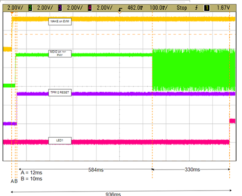
  • It takes 584ms to see any activity on the MDIO data line. In other words, it takes 584ms from the RESET signal going HIGH to show any data on the MDIO line. I assume this is the point at which the MCU is powered on and ready to communicate to the PHY, correct? Is this time interval too long?
  • It takes 330ms for the PHY to be configured as a master(It starts off as slave) and link with another PHY. This interval of 330ms shows a stream of MDIO data being sent to the PHY and at some point of this data, I assume a master configuration signal is being sent. Is there a way to check when this specific configuration signal is sent? I assume there are other instructions being sent besides the master configuration.
  • Hi David,

    Thanks for reaching out. I will get back on this request. Can you please provide some more information on this further:

    1. Whats the SW SDK you are using ?

    2. Is the application something similar to as described in Figure 10.1 of (https://www.ti.com/lit/ds/symlink/dp83tc812r-q1.pdf) ?

    Best Regards, Shiv 

  • 1) I am using the AM273x MCU+ SDK 

    2)  The application is similar. There are additional steps in the wakeup sequence. After the INH pin of the PHY is driven high and enables the 1st stage  buck, the buck's power good is used to enable a PMIC device. This PMIC device then starts the bootup process of the MCU via a reset signal as well as supplying 1V, 1.2V, and 1.8V rails. When successfully booted up, the MCU will configure the PHY as master so it can link to the host PHY.

    I will provide a figure for my measurements so far. It records 4 signals:

    • Wake on Host PHY(Yellow)
    • MDIO data line on MCU (Green)
    • Reset Signal of MCU (Purple)
    • LED1 on PHY to indicate successful linkage (Red)

    Some notes:

    • The MDIO of the MCU goes high at first because it is tied to a 3.3V signal.
    • I believe region of 584ms is how long it takes for the MCU to start its bootup process and finally start communication with the PHY. Is this a correct statement? I see that the MDIO data rises immediately after this 584ms, so I wonder if this time of 584ms can be reduced with optimized firmware to speed up the wakeup process of the MCU? If so, is it available for me to download?
    • I believe the region of 330ms is the time it takes for the PHY to be configured as master and link up to the host PHY. The MDC of the device right MCU right now is 2.2MHz even though the PHY supports MDCs of up to 25MHz. Am I correct in saying that the AM2732 does not support MDCs of up to 25MHz? A higher MDC would reduce this time of 330ms I believe.
  • Hi David, 

    Thanks for sharing the details. I will check internally with team and on TI EVM for boot to see :

    1.  Take one Eth example from MCU Plus SDK and check SBL + APP Download time. 

    2. Take one Eth example from MCU Plus SDK and see time it takes to get the MDIO data line to toggle from Reset.

    3. Check MDIO CLK configured value. MDIO_CONTROL_REG can be used to set the clock to desired value. 

    Other thing is that which example you are using from MCU+SDK. I will try to use similar/close to what you are using.

    Best Regards, Shiv

  • Howdy.

    Thanks I will try what you have suggested. Do you know what file the MDIO CLK value is commonly found in?

    I believe the example this project is using is Networking/LwIP.

  • Hi David, SBL execution (237KB) and Loading of the lwip application (~240KB) time is around: 17299us.

    Starting QSPI Bootloader ...
    [BOOTLOADER_PROFILE] Boot Media : NOR SPI FLASH
    [BOOTLOADER_PROFILE] Boot Media Clock : 80.000 MHz
    [BOOTLOADER_PROFILE] Boot Image Size : 237 KB
    [BOOTLOADER_PROFILE] Cores present :
    r5f0-0
    [BOOTLOADER PROFILE] System_init : 675us
    [BOOTLOADER PROFILE] Drivers_open : 32us
    [BOOTLOADER PROFILE] Board_driversOpen : 2738us
    [BOOTLOADER PROFILE] CPU load : 13851us
    [BOOTLOADER_PROFILE] SBL Total Time Taken : 17299us

    Image loading done, switching to application ...

    I am adding instrumentation to LWIP app image to do profiling to see how much time it takes. Will update once I have that result. 

    Best Regards, Shiv 

  • Hi David,

    I am working on this still, will have results by Tue (9/30).

    Best Regards, Shiv

  • Hi David, 

    I see 115 ms from NRESET to Successful ENET driver open ( Which means that PHY is detected and alive already). SBL Size here is 92614 bytes & APP Image size is 419176 bytes. Additionally I measured time for the link up and IP acquire time and that is around 136ms. Hope this helps. 

    So 584ms and 330ms look higher. I used the latest SDK for this. Can you please check from your side with the lwip example and default SBL what you see ?

    Best Regards, Shiv