Other Parts Discussed in Thread: HALCOGEN
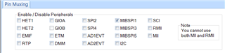
Hi, I tried to implement a data exchange on MIBSPI1 by connecting the board's SIMO[0] MIBSPI1 line with the SOMI[0] MIBSPI1 port.
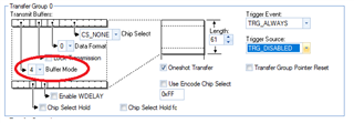
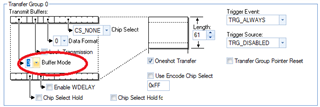
In Halcogen I selected these settings:
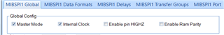
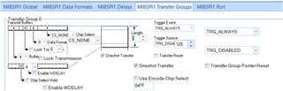
I want to transfer 10 FRAME of 61 ELEMENT each.
This is the implemented DMA and MIBSPI configuration:
void dmaConfigCtrlTxPacket(uint32 sadd,uint32 dadd,uint16 ElmntCnt, uint16 FrameCnt)
{
g_dmaCTRLPKT_TX.SADD = sadd; /* source address */
g_dmaCTRLPKT_TX.DADD = dadd; /* destination address */
g_dmaCTRLPKT_TX.CHCTRL = 0; /* channel control */
g_dmaCTRLPKT_TX.FRCNT = FrameCnt; /* frame count */
g_dmaCTRLPKT_TX.ELCNT = ElmntCnt; /* element count */
g_dmaCTRLPKT_TX.ELDOFFSET = 4; /* element destination offset */
g_dmaCTRLPKT_TX.ELSOFFSET = 0; /* element source offset */
g_dmaCTRLPKT_TX.FRDOFFSET = 0; /* frame destination offset */
g_dmaCTRLPKT_TX.FRSOFFSET = 0; /* frame destination offset */
g_dmaCTRLPKT_TX.PORTASGN = 4; /* port b */
g_dmaCTRLPKT_TX.RDSIZE = ACCESS_16_BIT; /* read size */
g_dmaCTRLPKT_TX.WRSIZE = ACCESS_16_BIT; /* write size */
g_dmaCTRLPKT_TX.TTYPE = FRAME_TRANSFER ; /* transfer type */
g_dmaCTRLPKT_TX.ADDMODERD = ADDR_INC1; /* address mode read */
g_dmaCTRLPKT_TX.ADDMODEWR = ADDR_OFFSET; /* address mode write */
g_dmaCTRLPKT_TX.AUTOINIT = AUTOINIT_ON; /* autoinit */
}
void dmaConfigCtrlRxPacket(uint32 sadd,uint32 dadd,uint16 ElmntCnt, uint16 FrameCnt)
{
g_dmaCTRLPKT_RX.SADD = sadd; /* source address */
g_dmaCTRLPKT_RX.DADD = dadd; /* destination address */
g_dmaCTRLPKT_RX.CHCTRL = 0; /* channel control */
g_dmaCTRLPKT_RX.FRCNT = FrameCnt; /* frame count */
g_dmaCTRLPKT_RX.ELCNT = ElmntCnt; /* element count */
g_dmaCTRLPKT_RX.ELDOFFSET = 0; /* element destination offset */
g_dmaCTRLPKT_RX.ELSOFFSET = 4; /* element source offset */
g_dmaCTRLPKT_RX.FRDOFFSET = 0; /* frame destination offset */
g_dmaCTRLPKT_RX.FRSOFFSET = 0; /* frame destination offset */
g_dmaCTRLPKT_RX.PORTASGN = 4; /* port b */
g_dmaCTRLPKT_RX.RDSIZE = ACCESS_16_BIT; /* read size */
g_dmaCTRLPKT_RX.WRSIZE = ACCESS_16_BIT; /* write size */
g_dmaCTRLPKT_RX.TTYPE = FRAME_TRANSFER ; /* transfer type */
g_dmaCTRLPKT_RX.ADDMODERD = ADDR_OFFSET; /* address mode read */
g_dmaCTRLPKT_RX.ADDMODEWR = ADDR_INC1; /* address mode write */
g_dmaCTRLPKT_RX.AUTOINIT = AUTOINIT_ON; /* autoinit */
}
void mibspiDmaConfig(mibspiBASE_t *mibspi,uint32 channel, uint32 txchannel, uint32 rxchannel)
{
uint32 bufid = E_COUNT - 1; //number of buffers in TG0
/* setting transmit and receive channels */
mibspi->DMACTRL[channel] |= (rxchannel << 20) | (txchannel << 16);
if (F_COUNT > 1) {
mibspi->TGCTRL[channel] &= 0xBFFFFFFF; // Disable ONESHOT
} else {
mibspi->TGCTRL[channel] |= 0x40000000; // Enable ONESHOT
}
/* enabling transmit and receive dma */
mibspi->DMACTRL[channel] |= 0x8000C000;
/* setting Initial Count of DMA transfers and the buffer utilized for DMA transfer */
mibspi->DMACTRL[channel] |= (bufid<<24);
/* setting Initial Count of DMA transfers and the buffer utilized for DMA transfer */
mibspi->DMACTRL[channel] |= ((F_COUNT - 1)<<8);
// /* setting Initial Count of DMA transfers and the buffer utilized for DMA transfer */
// mibspi->DMACTRL[channel] |= (0<<31);
//
// mibspi->DMACNTLEN = 0x1;
// mibspi->DMACOUNT[channel] = (F_COUNT - 1) << 16;
}
If I start the program the transfer occurs correctly, but with the oscilloscope, I see that the clock and MOSI lines continue to send data despite the fact that the transmission should be finished since I receive the block transfer complete interrupt. Is this behavior normal or is there something wrong with the configuration or implementation?
Attached is the complete sys_main.c for further analysis.
/** @file sys_main.c
*   @brief Application main file
*   @date 11-Dec-2018
*   @version 04.07.01
*
*   This file contains an empty main function,
*   which can be used for the application.
*/

/*
* Copyright (C) 2009-2018 Texas Instruments Incorporated - www.ti.com
*
*
*  Redistribution and use in source and binary forms, with or without
*  modification, are permitted provided that the following conditions
*  are met:
*
*    Redistributions of source code must retain the above copyright
*    notice, this list of conditions and the following disclaimer.
*
*    Redistributions in binary form must reproduce the above copyright
*    notice, this list of conditions and the following disclaimer in the
*    documentation and/or other materials provided with the
*    distribution.
*
*    Neither the name of Texas Instruments Incorporated nor the names of
*    its contributors may be used to endorse or promote products derived
*    from this software without specific prior written permission.
*
*  THIS SOFTWARE IS PROVIDED BY THE COPYRIGHT HOLDERS AND CONTRIBUTORS
*  "AS IS" AND ANY EXPRESS OR IMPLIED WARRANTIES, INCLUDING, BUT NOT
*  LIMITED TO, THE IMPLIED WARRANTIES OF MERCHANTABILITY AND FITNESS FOR
*  A PARTICULAR PURPOSE ARE DISCLAIMED. IN NO EVENT SHALL THE COPYRIGHT
*  OWNER OR CONTRIBUTORS BE LIABLE FOR ANY DIRECT, INDIRECT, INCIDENTAL,
*  SPECIAL, EXEMPLARY, OR CONSEQUENTIAL DAMAGES (INCLUDING, BUT NOT
*  LIMITED TO, PROCUREMENT OF SUBSTITUTE GOODS OR SERVICES; LOSS OF USE,
*  DATA, OR PROFITS; OR BUSINESS INTERRUPTION) HOWEVER CAUSED AND ON ANY
*  THEORY OF LIABILITY, WHETHER IN CONTRACT, STRICT LIABILITY, OR TORT
*  (INCLUDING NEGLIGENCE OR OTHERWISE) ARISING IN ANY WAY OUT OF THE USE
*  OF THIS SOFTWARE, EVEN IF ADVISED OF THE POSSIBILITY OF SUCH DAMAGE.
*
*/


/* USER CODE BEGIN (0) */
/* USER CODE END */

/* Include Files */

#include "sys_common.h"

/* USER CODE BEGIN (1) */
#include "mibspi.h"
#include "sys_dma.h"
#include "stdio.h"
#include "sys_core.h"
/* USER CODE END */

/** @fn void main(void)
*   @brief Application main function
*   @note This function is empty by default.
*
*   This function is called after startup.
*   The user can use this function to implement the application.
*/

/* USER CODE BEGIN (2) */
void mibspiDmaConfig(mibspiBASE_t *mibspi,uint32 channel, uint32 txchannel, uint32 rxchannel);
void dmaConfigCtrlRxPacket(uint32 sadd,uint32 dadd,uint16 ElmntCnt, uint16 FrameCnt);
void dmaConfigCtrlTxPacket(uint32 sadd,uint32 dadd,uint16 ElmntCnt, uint16 FrameCnt);
void loadDataPattern1(uint32 psize, uint16* pptr);
void loadDataPattern2(uint32 psize, uint16* pptr);
#define E_COUNT      61  //4   /*Element count*/
#define F_COUNT      10   //2   /*Frame count*/
#define D_SIZE      E_COUNT * F_COUNT

/* SPI1 transmit buffer in sys ram */
uint16 mibSPI1_TX_Data[D_SIZE];//= "$GPZDA,hhmmss.ss,dd,mm,yyyy,aa,bb*CS<CR><LF>$GPGLL,llll.lllll,a,yyyyy.yyyyy,b,hhmmss.ss,c,a*CS<CR><LF>$GPGSV,t,n,xx,aa,ee,zzz,cc,aa,ee,zzz,cc,aa,ee,zzz,cc,aa,ee,zzz,cc*CS<CR><LF>$GPRMC,hhmmss.ss,A,llll.lllll,A,yyyyy.yyyyy,B,ssss.ss,hhh.hh,ddmmyy,mm.m,D,B*CS<CR><LF>$GPGGA,hhmmss.ss,llll.lllll,A,yyyyy.yyyyy,B,q,nn,hh.h,aaaaa.a,M,sss.s,M,a.a,aaaa*CS<CR><LF>$GPGSA,a,m,s1,s2,s3,s4,s5,s6,s7,s8,s9,s10,s11,s12,pp.p,hh.h,vv.v*CS<CR><LF>$GPVTG,ddd.dd,T,ddd.dd,M,ssss.ss,N,ssss.ss,K,a*CS<CR><LF>";
/* SPI2 transmit  buffer in sys ram */
/* SPI1 receive buffer in sys ram */
uint16 mibSPI1_RX_Data[D_SIZE]= {0};
/* SPI2 receive  buffer in sys ram */

g_dmaCTRL g_dmaCTRLPKT_RX;  /* dma control packet configuration stack for receive */
g_dmaCTRL g_dmaCTRLPKT_TX;  /* dma control packet configuration stack for transmit */

typedef enum dmaRequest
{
    DMA_REQ0 = 0U,  DMA_REQ1,   DMA_REQ2,   DMA_REQ3,
    DMA_REQ4,       DMA_REQ5,   DMA_REQ6,   DMA_REQ7,
    DMA_REQ8,       DMA_REQ9,   DMA_REQ10,  DMA_REQ11,
    DMA_REQ12,      DMA_REQ13,  DMA_REQ14,  DMA_REQ15,
    DMA_REQ16,      DMA_REQ17,  DMA_REQ18,  DMA_REQ19,
    DMA_REQ20,      DMA_REQ21,  DMA_REQ22,  DMA_REQ23,
    DMA_REQ24,      DMA_REQ25,  DMA_REQ26,  DMA_REQ27,
    DMA_REQ28,      DMA_REQ29,  DMA_REQ30,  DMA_REQ31,
    DMA_REQ32,      DMA_REQ33,  DMA_REQ34,  DMA_REQ35,
    DMA_REQ36,      DMA_REQ37,  DMA_REQ38,  DMA_REQ39,
    DMA_REQ40,      DMA_REQ41,  DMA_REQ42,  DMA_REQ43,
    DMA_REQ44,      DMA_REQ45,  DMA_REQ46,  DMA_REQ47
}dmaRequest_t;

unsigned MIBSPI_DMA_FLG;
/* USER CODE END */

int main(void)
{
/* USER CODE BEGIN (3) */
    uint32 i;

    _enable_interrupt_();

    /* - initializing mibspi - enabling Transfer Group 0 , length 128 (halcogen file)*/
    mibspiInit();
    dmaDisable();

    loadDataPattern1(D_SIZE, &mibSPI1_TX_Data[0]);

/*****************************************************************/
    /* - configuring dma control packet for sending data to mibSPI3 tx buffer*/
    dmaConfigCtrlRxPacket((uint32)&(mibspiRAM1->rx[0].data),(uint32)&(mibSPI1_RX_Data), E_COUNT, F_COUNT);
    /* - configuring dma control packet for receiving data from mibSPI3 rx buffer*/
    dmaConfigCtrlTxPacket((uint32)&(mibSPI1_TX_Data),(uint32)&(mibspiRAM1->tx[0].data), E_COUNT, F_COUNT);

    /* - setting dma control packets for transmit */
    dmaSetCtrlPacket(DMA_CH1, g_dmaCTRLPKT_TX);
    /* - setting dma control packets for Receive */
    dmaSetCtrlPacket(DMA_CH0, g_dmaCTRLPKT_RX);

    /* DMA Request Sources: MIBSPI1[0] -> DMA request 1 */
    dmaReqAssign(DMA_CH1, DMA_REQ9 );    /* Transmit data DMA channel enable. Request line=0*/
    /* DMA Request Sources: MIBSPI1[1] -> DMA request 0 */
    dmaReqAssign(DMA_CH0, DMA_REQ8 );    /* Receive data DMA channel enable. Request Line=1. */

    /* - setting the dma channel to trigger on h/w request */
    dmaSetChEnable(DMA_CH1, DMA_HW);
    dmaSetChEnable(DMA_CH0, DMA_HW);

    /* - configuring the mibspi dma , channel 0 , tx line -0 , rxline -1     */
    /* - refer to the device data sheet dma request source for mibspi tx/rx  */
    mibspiDmaConfig(mibspiREG1, 0, 5, 4);

    /* Enable Block Transfer Complete interrupt for the receive after transfer complete */
    dmaEnableInterrupt(DMA_CH0, BTC);  //MibSPI1 RX

/****************************************************************/


/****************************************/

    /* enable DMA now to make sure it's ready to take requests   */
    dmaEnable();

//    mibspiSetData(mibspiREG1, 0, &mibSPI1_TX_Data[0]);
//    mibspiSetData(mibspiREG3, 0, &mibSPI3_TX_Data[0]);

    for(i=0;i<=20;i++){printf("\n%dA",i);}
    mibspiTransfer(mibspiREG1, 0);
    while(MIBSPI_DMA_FLG == 0);

    for(i=0;i<=D_SIZE;i++)
    {
        printf("\r\n%d mibSPI1_TX_Data: 0x%04x mibSPI1_RX_Data: 0x%04x  ",i, mibSPI1_TX_Data[i], mibSPI1_RX_Data[i]);
    }
    while(1);
/* USER CODE END */

    return 0;
}


/* USER CODE BEGIN (4) */
void dmaGroupANotification(dmaInterrupt_t inttype, uint32 channel)
{
   MIBSPI_DMA_FLG = 1;
}

void dmaConfigCtrlTxPacket(uint32 sadd,uint32 dadd,uint16 ElmntCnt, uint16 FrameCnt)
{
    g_dmaCTRLPKT_TX.SADD      = sadd;              /* source address             */
    g_dmaCTRLPKT_TX.DADD      = dadd;              /* destination  address       */
    g_dmaCTRLPKT_TX.CHCTRL    = 0;                 /* channel control            */
    g_dmaCTRLPKT_TX.FRCNT     = FrameCnt;                 /* frame count                */
    g_dmaCTRLPKT_TX.ELCNT     = ElmntCnt;             /* element count              */
    g_dmaCTRLPKT_TX.ELDOFFSET = 4;                 /* element destination offset */
    g_dmaCTRLPKT_TX.ELSOFFSET = 0;                 /* element source offset */
    g_dmaCTRLPKT_TX.FRDOFFSET = 0;                 /* frame destination offset   */
    g_dmaCTRLPKT_TX.FRSOFFSET = 0;                 /* frame destination offset   */
    g_dmaCTRLPKT_TX.PORTASGN  = 4;                 /* port b                     */
    g_dmaCTRLPKT_TX.RDSIZE    = ACCESS_16_BIT;     /* read size                  */
    g_dmaCTRLPKT_TX.WRSIZE    = ACCESS_16_BIT;     /* write size                 */
    g_dmaCTRLPKT_TX.TTYPE     = FRAME_TRANSFER ;   /* transfer type              */
    g_dmaCTRLPKT_TX.ADDMODERD = ADDR_INC1;         /* address mode read          */
    g_dmaCTRLPKT_TX.ADDMODEWR = ADDR_OFFSET;       /* address mode write         */
    g_dmaCTRLPKT_TX.AUTOINIT  = AUTOINIT_ON;       /* autoinit                   */
}

void dmaConfigCtrlRxPacket(uint32 sadd,uint32 dadd,uint16 ElmntCnt, uint16 FrameCnt)
{
    g_dmaCTRLPKT_RX.SADD      = sadd;              /* source address             */
    g_dmaCTRLPKT_RX.DADD      = dadd;              /* destination  address       */
    g_dmaCTRLPKT_RX.CHCTRL    = 0;                 /* channel control            */
    g_dmaCTRLPKT_RX.FRCNT     = FrameCnt;                 /* frame count                */
    g_dmaCTRLPKT_RX.ELCNT     = ElmntCnt;             /* element count              */
    g_dmaCTRLPKT_RX.ELDOFFSET = 0;                 /* element destination offset */
    g_dmaCTRLPKT_RX.ELSOFFSET = 4;                 /* element source offset */
    g_dmaCTRLPKT_RX.FRDOFFSET = 0;                 /* frame destination offset   */
    g_dmaCTRLPKT_RX.FRSOFFSET = 0;                 /* frame destination offset   */
    g_dmaCTRLPKT_RX.PORTASGN  = 4;                 /* port b                     */
    g_dmaCTRLPKT_RX.RDSIZE    = ACCESS_16_BIT;     /* read size                  */
    g_dmaCTRLPKT_RX.WRSIZE    = ACCESS_16_BIT;     /* write size                 */
    g_dmaCTRLPKT_RX.TTYPE     = FRAME_TRANSFER ;   /* transfer type              */
    g_dmaCTRLPKT_RX.ADDMODERD = ADDR_OFFSET;       /* address mode read          */
    g_dmaCTRLPKT_RX.ADDMODEWR = ADDR_INC1;         /* address mode write         */
    g_dmaCTRLPKT_RX.AUTOINIT  = AUTOINIT_ON;       /* autoinit                   */
}

void mibspiDmaConfig(mibspiBASE_t *mibspi,uint32 channel, uint32 txchannel, uint32 rxchannel)
{
    uint32 bufid  = E_COUNT - 1;  //number of buffers in TG0

    /* setting transmit and receive channels */
    mibspi->DMACTRL[channel] |= (rxchannel << 20) | (txchannel << 16);

    if (F_COUNT > 1) {
         mibspi->TGCTRL[channel] &= 0xBFFFFFFF; // Disable ONESHOT
    } else {
         mibspi->TGCTRL[channel] |= 0x40000000; // Enable ONESHOT
    }

    /* enabling transmit and receive dma */
    mibspi->DMACTRL[channel] |=  0x8000C000;

    /* setting Initial Count of DMA transfers and the buffer utilized for DMA transfer */
    mibspi->DMACTRL[channel] |=  (bufid<<24);

    /* setting Initial Count of DMA transfers and the buffer utilized for DMA transfer */
    mibspi->DMACTRL[channel] |=  ((F_COUNT - 1)<<8);

//    /* setting Initial Count of DMA transfers and the buffer utilized for DMA transfer */
//    mibspi->DMACTRL[channel] |=  (0<<31);
//
//    mibspi->DMACNTLEN = 0x1;
//    mibspi->DMACOUNT[channel] = (F_COUNT - 1) << 16;
}

void loadDataPattern1(uint32 psize, uint16* pptr)
{
    int i;
    for(i=0;i<psize;i++)
    {
        pptr[i] = i;
    }
 }

void loadDataPattern2(uint32 psize, uint16* pptr)
{
    int i;
    int j = 0;
    for(i=psize;i>0;i--)
    {
        pptr[j] = i;
        j++;
    }
 }

/* USER CODE END */
Thank you in advance for your help.