


Part Number: AM2434
Other Parts Discussed in Thread: DP83826E
Hi Expert,
I am testing CLKOUT0 of AM2434 on our product board.
I tried to enable CLKOUT0 to generate 25Mhz clock output from AM2434, which is connected to the clock-in(XI) of the ethernet PHY chip (TI DP83826E) in our product board.
The test code was implemented in the system startup routine like below, referring to the CTRLMMR_CLKOUT_CTRL address from TRM and existing code from SDK.
    // after hw initialization

    SOC_controlModuleUnlockMMR( SOC_DOMAIN_ID_MAIN, 2 );
    *(volatile uint32_t*)(0x43008010U) = 0x11U; // 0x10u (enable CLKOUT0) and 0x01 (25Mhz)
    SOC_controlModuleLockMMR(SOC_DOMAIN_ID_MAIN, 2);

    // before starting task
CTRLMMR_CLKOUT_CTRL in TRM:

I checked in CCS that the CTRLMMR_CLKOUT_CTRL register is correctly set with the code above as below,
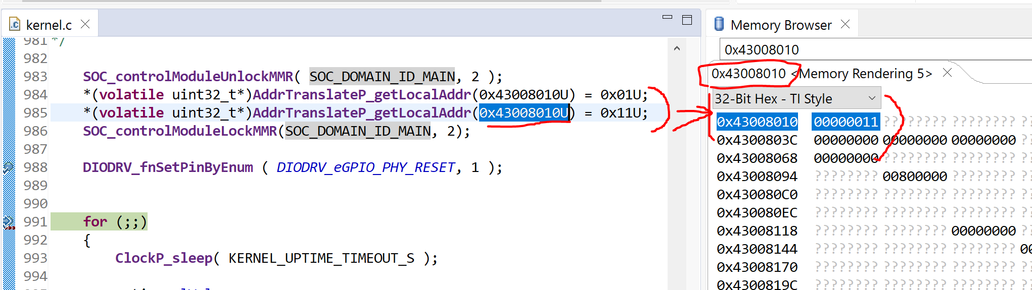
However, when I checked the test pin connected to U13(CLKOUT0) of AM2434, I was not able to see the clock output.
Should I set PADCONFIG related to U13? if yes, please let me know which PADCONFIG register should be set. I think we can use Pinmux_config() to config the pinmux for CLKOUT0 like the ones in "ti_pinmux_config.c". Please let me know if this is the correct way.
Could you share your experience and knowledge on this? Any checkpoint for correctly enabling it will help my progress.
Regard,
Moonil
