This thread has been locked.

If you have a related question, please click the "Ask a related question" button in the top right corner. The newly created question will be automatically linked to this question.

MSP432E401Y: Hibernation current consumption

Part Number: MSP432E401Y

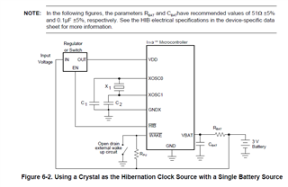
We can measure the power consumption in hibernation 43 uA at VBAT. As we understand we cannot control the pins and set them during hibernation. Why would the hibernation module consume so much power, we need RTC and we use externa crystal 32kHz, but still according to the datasheet the typical power consumption is 1.29 uA. Any tips are appreciated.

  • Hi,

      I have some questions.

      - Are you in VDD3ON mode with the I/Os in retention?

      - Are you running your own application software or the SDK hibernate example?

      - Can you confirm if you run the SDK hibernate example, you are getting similar current like 43uA. This is to isolate if there is an issue with the software.

      - Can you run your own application and the SDK hibernate example on the LaunchPad evm board? Will you achieve only 43uA or much lower?

      - Do you have multiple of your custom boards you can try out? Are you getting similar results?

  • - We are using hibernate mode and we can verify with oscilloscope that the I/Os are not retained.
    - We used TI example code to write our own application software. We have only the button press as a wake condition. 

    - Trying to run our own code on the LaunchPad evm board we get much lower current. We have the same hardware design for the Hibernate module marked as U1C as the PCB schematics for the Launchpad board, pdf slau748b.pdf User's guide. And I am not sure what else can be on as we only have power to this Hibernate module. And VBAT is powering this module. 
    - To difference from the Launchpad we do not have anything connected to pins 53, 54, 56, 57. Can this be anything we might consider ? 
    We tried on several of our custom boards and we get the same result for the current in hibernate. 

  • We found out the high level on WAKE_N pin is 1,2V. And we measure above 3V on the Launchpad with the same code.
    Do you know or can we find somewhere information about how much the power should be on wake pin to keep the signal high. Maybe we had our board in some transition mode and WAKE_n pin was not high enough to be in hibernate

  • - Trying to run our own code on the LaunchPad evm board we get much lower current.

    So it is not a software issue as you can run your own software on LP and get much lower current. 

    To difference from the Launchpad we do not have anything connected to pins 53, 54, 56, 57. Can this be anything we might consider ?

    Per recommendation, if Ethernet is not used, they are left as NC for pin 53, 54, 56, 57. 

    We found out the high level on WAKE_N pin is 1,2V. And we measure above 3V on the Launchpad with the same code.

    1.2V is more like floating. For experiment purpose, can you tie it high to 3.3V and do you see see higher current?

    Below is the recommended circuit depicted in the datasheet. Is your WAKE_n pin built similar to the below?

  • Yes, we increased the voltage on pin WAKE_N to 2.25V and then the current on VBAT goes down to 1,23 uA (from 43uA). This seems ok.
    But now we have a problem with the current on pin RST_N. The current in hibernation into this pin is 12,4 uA and we do not have voltage to VDD. This current is way too high. We use separate power for VBAT which is 2.3V. We have pull-up resistor for RST_N which is connected to 2,3V. Can it be a problem for the current going into the RST_N pin when VDD = 0V. The Launchpad has always voltage on VDD and very low current into pin 70 (RST_N). 

  • Yes, we increased the voltage on pin WAKE_N to 2.25V and then the current on VBAT goes down to 1,23 uA (from 43uA). This seems ok.

    Glad that to hear it. 

    But now we have a problem with the current on pin RST_N. The current in hibernation into this pin is 12,4 uA and we do not have voltage to VDD.

    I'm a bit confused. Earlier you just said you were achieving 1.23uA for current on VBAT. Are you saying you measured two different currents to the MCU during hibernation?

    Can it be a problem for the current going into the RST_N pin when VDD = 0V. The Launchpad has always voltage on VDD and very low current into pin 70

    Do you have RST_N configured as one of the wake sources?

    I'm not too sure if 2.3V on RST is too low to meet the Vih of the pin. Can you for experiment raise the voltage on RST_N higher and will that give you a better result? With RST_N equal to 0V then it may become a wake event if you had configured RST_N as another wake source. 

  • Hi, thank you for your reply.

    Quote: " I'm a bit confused. Earlier you just said you were achieving 1.23uA for current on VBAT. Are you saying you measured two different currents to the MCU during hibernation?"

    -   We had a resistor which was leaking current to a contact and this was why we had too high current at VBAT so the current changed from 43uA to 1.23uA. When we removed this resistor, we got 1.23uA. This resistor was connected to a pin which would generate a wake source because this pin is also connected to WAKE_N and can drive pin WAKE_N low. We were concerned when we measured the currrent at pin 70 and got 12.4 uA. We think it is too high. There might be current leakage to this pin or some other issue.

    Can it be a problem for the reset pin if there is so high current, we were thinking it can cause problems for the final product. I could not find information about typical current going to the reset pin in hibernation in the technical reference for CPU MSP432E401Y. 

    Quote: "Do you have RST_N configured as one of the wake sources?"
    We do not have RST_N pin as a wake source. This reset pin is only connected to the debug contact via a diode and to the current source in hibernation via resistor of 100k.  

    Regards, 

    Gergana Tanova

  • Hi,

    We were concerned when we measured the currrent at pin 70 and got 12.4 uA. We think it is too high. There might be current leakage to this pin or some other issue.

    Can it be a problem for the reset pin if there is so high current, we were thinking it can cause problems for the final product. I could not find information about typical current going to the reset pin in hibernation in the technical reference for CPU MSP432E401Y. 

    I really don't have an idea as to what caused the RST_N pin to have higher current during hibernation. Did you have a chance to pullup RST_N to VDD instead of VBAT as an experiment? 

    We do not have RST_N pin as a wake source. This reset pin is only connected to the debug contact via a diode and to the current source in hibernation via resistor of 100k.  

    I don't see a problem with a 100k resistor. It needs to be pullup even though you don't use RST_N as a wake source. If the RST_N pin ls low then you will put the device in reset when you are in run mode. 

  • I really don't have an idea as to what caused the RST_N pin to have higher current during hibernation. Did you have a chance to pullup RST_N to VDD instead of VBAT as an experiment? 

    We can try that!

    Meanwhile, we tried to lower resistor value for the resistor connected to RST_N to 10k and then to 4.7k. The result was we had even higher current to pin 70 compared to when we had resistor = 100k. We do not have the exact figures though.

    On our consumer board, with a resistor of 100k the hibernate current into pin 70 was 12.4uA and 80nA in drift. 


    When we changed the resistor on LaunchPad to10k we got the current, 54nA in drift. We tried two different cases in hibernation for the Launchpad: when VDD is 3.3V and when VDD is 0V.

    The result is 42nA when VDD = 3.3V and 59.2uA when VDD = 0V. 

    There seems to be difference for the current into pin 70 when VDD is removed. Do you know anything about that? Maybe we cannot get low current when VDD = 0V?

  • Hello again,

    We have a simplified schematics to our board, attached below. Our problem is that the current into pin 70 is too high. Maybe you can see probable errors. 

  • Hi,

      Sorry, I wish I could help identify the cause of the subtle high current. All I can tell is that there is some difference between your implementation for RST_N and WAKE_N on your circuit vs. the LaunchPad. Since the LaunchPad is giving the desired current consumption during hibernate mode, is it possible for you to mimic the same?

  • Thank you for the reply. What do you mean more precisely by the different implementation of those pins? 
    We wanted to do the implementation according to the technical reference manual  called slau723a.pdf, Chapter 6 Hibenation module. We want to use an external regulator which is connected to HIB_N and can remove VDD during hibernate so we can have a very low power consumption. It is figure 6-4, page 481 in the document. 

  • Hi,

      The small difference I see is that you have the PN5 connecting to the WAKE_N via a diode. What is the purpose of PN5? During hibernate, the state of I/Os is not retained. You may or may not turn on the diode. I also see RST_N and WAKE_N pulled up to ALWAYS_2V3. I'm interested to know what happens if you pull up to 3V. 

  • Hi,

      I wanted to give you a heads-up that I will be out of office until next Tuesday.

  • We use PN5 to read the button press after we have waken from hibernation. 

    We tried to connect pull up to 3.3V on the LaunchPad. If we look at the datasheet for the launchpad, R39 was disconnected. R38, R42 and R44 were connected to +3V3 all the time. All VDD pins were without any power because we lifted jumper JP2. The result was that current consumption through R44 (RESET pull-up) went up from 42nA to 59.2uA.

  • Hi Gergana,

      Sorry, I was out of office and just got back. 

    All VDD pins were without any power because we lifted jumper JP2. The result was that current consumption through R44 (RESET pull-up) went up from 42nA to 59.2uA.

    Is this on your own custom board or on the LaunchPad board? The LP board has JP2. Does your custom board have it too? Just wanted to make sure we are talking about the same board. 

       I kind of run out ideas as to where the problem is. What would you measure on TGT_RST on LP to TARGET_RESET vs your board after you remove JP2?

  • No problem.

    Is this on your own custom board or on the LaunchPad board? The LP board has JP2. Does your custom board have it too? Just wanted to make sure we are talking about the same board.

    I talked about the launchpad and a test we did on it

    The customer board does not have JP2. But we wanted to try on the Launchpad if we removed VDD current what will happen to the current at the Reset pin. The current consumption on the reset pin is high as in the case of our custom board when we have VDD = 0V.

    I can get back to you with measurements for TGT_RST.

  • Hi, I just wanted to update you on our case. 

    Now we have connected RST pin 70 to VDD on our consumer board. This means that in hibernation, the reset pin does not have any power. We managed to decrease the power consumption to 8uA as a result.

    Our conclusion is that RST pin 70 cannot be connected to any other power source except for VDD and does not need to be powered in Hibernation in order to keep the pin high. 

  • Hi Gergana,

      Really glad that you are able to achieve 8uA. As I asked earlier, if you are not using RST as a wakeup source then not have power on RST should be fine. I will mark this thread as closed and also sorry for the late reply as I was out of office yesterday. 

  • yeah, hopefully it will be of help to other developers. 

    Thanks for the support!