This thread has been locked.

If you have a related question, please click the "Ask a related question" button in the top right corner. The newly created question will be automatically linked to this question.

AM2634-Q1: AM263x ADC Calibration Question

Part Number: AM2634-Q1
Other Parts Discussed in Thread: C2000WARE

Hi expert:

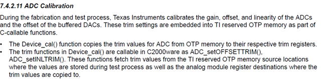
     I have a question regarding how to perform ADC calibration. In the TRM, it still describe the procedure using C2K APIs.  These APIs can not be found in MCU+ SDK for AM263x

Question 1: Where we store the calibration information? What is its structure?

Question 2: What are the steps to perform ADC calibration? 

Question 3: Will we support calibration in SDK in the future?

Regards

Andre

  • Hello Andre,

    In C2000 the trim settings (bits) for ADC are stored in a OTP location (such as 0x70128 in F2838x) and C2000Ware provided driver functions (such as ADC_setINLTRIM, ADC_setOFFSETTRIM) to read the trim bits from OTP locations and write into ADC TRIM registers

    In AM263x, this step (copying of trim bits to ADC TRIM registers) is performed by hardware during power up sequence.
    So in AM263x MCU SDK, we do not require/support the above calibration functions to copy the trim bits to ADC TRIM registers

    Question 1: Where we store the calibration information? What is its structure?

    Calibration information is stored in TOP_CTRL registers and copied to ADC registers ADCINLTRIM1-6 (offsets 0xE0-0xF4) during power up

    Question 3: Will we support calibration in SDK in the future?

    Above mentioned calibration functions are not required for AM263x and hence no plan to support in SDK

    Question 2: What are the steps to perform ADC calibration? 

    I'll get back on this - specifically calibration using CAL0, CAL1 pins

    Thanks

    Sanjeev

  • Sanjeev,

         Thanks for your reply but more questions?

    Question 1: Where we store the calibration information? What is its structure?

    According to response, calibration information is stored in TOP_CTRL registers? Can register store the permanent data? The trim information should be store in EEPROM/FLASH  or somewhere else so HW or RBL can load it during power up.  I still don't get you how AM263x store trim information per chip basis.  Can you please provide more information?

      Many sections are still using C2K description and misleading customers. When can we release revised TRM to customer?

    Regards

    Andre 


  • Hello Andre,

    The CAL pins on the ADC is more used for the system level Calibration/qualification of ADC. One can provide a 'known' value to the CAL Channel and qualify ADC during run time, this is expected to be done through code rather than hardware itself. For example, say, a 100mV and 3V are provided to these and are recorded from the 5 ADCs. based on these values, the full signal path gain/offset (including external amplifier/buffer/filter) may be calibrated. TRIM defaults are loaded at power on and there is no intervention needed.

    Thanks,

    Madhava

  • Madhava,

           Thanks for your reply but I have questions. Since draft still use C2K to describe ADC function,  I suppose AM263x ADC will use the same trim process as C2K. Before we ship C2K chip to customer, we will trim ADC in factory and store this trim data into on-chip OTP. This trim data is per chip basis. 

    Q1: Does  every AM263x  chip perform the same trim process in factory?

    Q2: If we do trim adc chip by chip, since this trim data need be stored permanently, where is it stored?

    Or, we don't perform per chip trim process in factory?

    Regards

    Andre   

  • Hi Andre

    From the information gathered from the hardware teams,

    “ The purpose of the CAL channels are more for system level calibration/qualification of the ADC. In the field customers can provide a ‘known’ value to one of the CAL channel and qualify the ADC in run time. They can also calibrate the whole channel gain/offset etc. using this. That calibration is outside C2K wrapper is and is expected to be done in customer software. For example they can provide cal0 with 100mV and cal1 with 3V input and record all the 5 ADC outputs in run time. Based on this output they can calibrate the full signal path gain/offset (including external driving amplifier/buffer/filter and also the reference voltages of the ADC). ”

    Regarding the ADC trim registers, as the experts already mentioned:

    “We do not do any trim as of now for ADCs same or different. The default untrimmed parts provided from the ADC spec performance based on silicon measurements”

     We have taken action on modifying the ADC Calibration data in TRM. A bug is filed to take action. – Bug ID for your reference - SITARAAPPS-2632

    Thanks & Regards

    Sri Vidya

  • Sri,

         The updated TRM which is released 2022/10/07 still uses wrong description. May I know the target date to fix TRM?

  • Hello Andre,

    These details have been removed and will be reflected in the rev D release (SPRUJ14D).

    Best Regards,

    Zackary Fleenor