This thread has been locked.

If you have a related question, please click the "Ask a related question" button in the top right corner. The newly created question will be automatically linked to this question.

TM4C123GH6PM: SPI SSImodule

Part Number: TM4C123GH6PM

I am trying to figure out if were to "activate" the SSI modules for SPI use, would it be possible to put the clock low during a portion of my code then set it high after I have gone through my process? 

My example code is below of what i am thinking. I have omitted most of the code as i just would like to see if it is possible to do what is highlighted in yellow. Also, toward the end of the example code i showed the initialization of the SSI1 module but omitted the entire process to make the message smaller.

For instance:

// Using SSI1 for SPI comm protocol on PORTD

int main(void)

{

...

...

{

GPIO_PORTD_DATA_R   &=   ~0x01;          // TO SET PORTD 0 SSI1 Clock low

...

...

...

GPIO_PORTD_DATA_R   |=   0x01;           //SET PORTD PIN 0 SSI1 Clock high

}

}

void init_SSI1(void)

{

SYSCTL_RCGCSSI_R |= 2;                           //enable clock to SSI1

SYSCTL_RCGCGPIO_R |= 8;                       //enable clock to GPIOD for SSI1

.....

.....

.....

}

  • Hi,

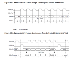
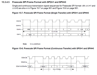
      I'm not sure what is the background of your application requiring you to manipulate SPICLK. When you activate or enable SSI module, the SSIClk, SSIFss and SSInTx are driven by the SSI module. Depending on the polarity and phase you select, the SSIClk will be low when it is not transmitting. Wouldn't that be sufficient for your SPI device? If your SPI device requires you to have the SPICLK high during idle then you can change the SPO and SPH for that protocol. See below SPO=0 and SPH=0. I don't think what you show in yellow will work. After SSI initiation, the PD0 pin becomes a SSI pin. Writing a 1 to the GPIO Data register for PD will not have an effect unless you change the multiplex back to GPIO mode. The reason is that multiple functions share the same PD0 pin. 

    With SPO=1 and SPH=0 the SSIClk is high during idle. 

  • What i am trying to do is write to an OLED display and the sample code the device used is written in an Audrino Uno. So I am trying to covert that code for the TM4C123 MCU.

    From what your illustration is saying I should use SPO = 0 and SPH = 0 if i want the clock to be low during idle, then it will go high when i am ready to write something to it? 

    And if that is the cause i wouldn't have to write the clock pin low (GPIO_PORTD_DATA_R &= ~0x01) because its already low.

  • From what your illustration is saying I should use SPO = 0 and SPH = 0 if i want the clock to be low during idle, then it will go high when i am ready to write something to it? 

    And if that is the cause i wouldn't have to write the clock pin low (GPIO_PORTD_DATA_R &= ~0x01) because its already low.

    Yes, use SPO=0 and SPH=0 which is what most of the SPI slave devices accept. 

    Also, I don't see you use TivaWare APIs but rather DRM (direct register manipulation) method of coding which we don't support. Take a look at the several SSI examples in TivaWare library. See examples in below folder. 

    C:\ti\TivaWare_C_Series-2.2.0.295\examples\peripherals\ssi

  • Thank you for the information. I figured out my issue. 


    Also, I've learned to go with DRM as the text I'm learning off of uses Keil software and I'm using CCS. I am not and expert with C yet so I'm learning more and more as I go.