Hello!
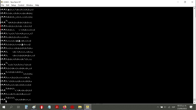
I have a problem with the UART transmission of my microcontroller, when sending data through the UART0
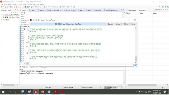
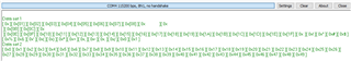
and observing it in the TERMITE terminal, some data strings are cut in half (image 1)
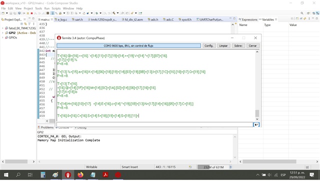
or with spaces in the strings (image 2), could you give me any suggestions to solve this? :)
Mayra
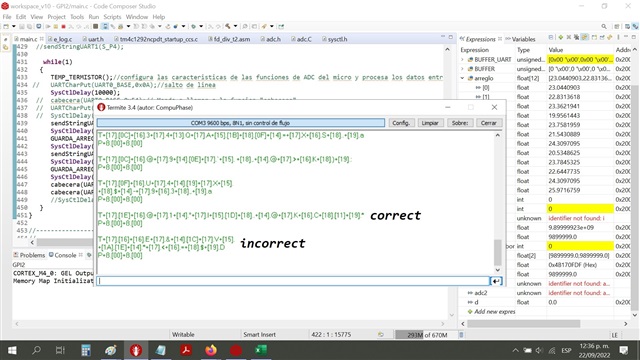
Image 1
image 2

-
Ask a related question
What is a related question?A related question is a question created from another question. When the related question is created, it will be automatically linked to the original question.