This thread has been locked.

If you have a related question, please click the "Ask a related question" button in the top right corner. The newly created question will be automatically linked to this question.

TMS570LC4357: Using HET IDE to generate phase aligned/locked clock from external clock

Part Number: TMS570LC4357
Other Parts Discussed in Thread: HALCOGEN

I've gone through the HET IDE tutorial and would like to implement a relatively simple clock generator.

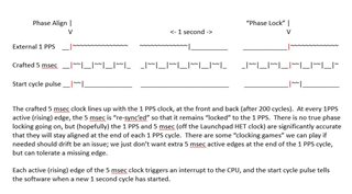
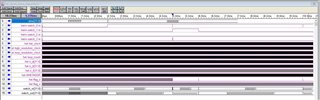
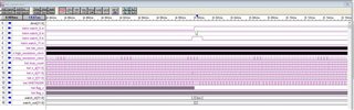
From an externally generated 1 PPS clock, I'd like to generate a 5 msec 50% duty cycle period clock that is phase aligned (and hopefully "locked") to the 1 PPS one.

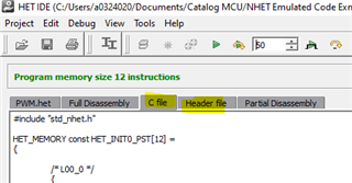
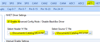
The Launchpad HET PWM project I've previously used produced a 5 msec clock (that generated periodic interrupts to the CPU) but it did not have any way to align to an external 1 PPS clock.  And hence the use of the HET IDE is fitting.  The microcode in HL_het.c in the HET PWM project seems to have more "meat" than I need, so I'm not sure "reverse engineering" it (is there any HET disassembler?) by the provided comments is that appropriate/useful.

Is there any HET IDE projects that could fast-track me to getting this done?  I see some stuff in the algorithm library, include PWM projects, but they seem more fancy than anything I need.

I will try to gain more familiarity with the HET instructions and engine, but I'm not one for re-inventing the wheel if  I can find a close-enough wheel to use as a start.

Thank you very much.

  • HI Peter,

    You can toggle one N2HET pin to enable/disable the external clock.

  • Hi, QJ,

    I don't understand what you mention about enabling/disabling the external clock.

    I probably wasn't clear about what I need to do.  Perhaps the timing diagram below would clarify.  I'm looking to have the HET generate a 5 msec clock that would stay aligned to a (precise and accurate) 1 PPS clock from an external source.

    This 5 msec cycle clock could run perpetually, although having an enable/disable may be nice to have.  We can (hopefully) use the usual edgeEnableNotification()/edgeDisableNotification() to manage the CPU interrupt.

    Thank you very much.

  • Hi Peter,

    I thought that the 1pps is generated by an external device which can be triggered by the rising or falling edge of a N2HET pin that is controlled by the N2HET code.

    Yes, you use a edge of a input signal to start the 5msec clock generation and 1pps generation.

  • Hi, QJ,

    RIght now, the external 1 PPS is not gated by any output signal from the Launchpad.  It is either an accurate 1 PPS signal (from a signal generator) or flat, but never a noise line (that could wreak havoc).  The 1 PPS is distributed to several Launchpad.

    The Launchpad only has to generate the 5 msec (200Hz) clock, but the 5-msec phase must be aligned (self-adjust every 200 cycles) to the incoming 1 PPS.

    I'm thinking the HET program would continually look for the active edge (transition) of the incoming 1 PPS, and restart its 5 msec clock generation at the 5-msec's active edge.

    Now, if only I could right the code to do this...

    Thanks.

  • You can use BR instruction to monitor the input signal. When rising edge is detected of pin #1, the code will jump to address Ly to start a counter to PWM signal:

    BR { next= Lx, cond_addr=Ly, event=RISE, pin= #1};

    Please refer to the description of N2HET instructions in device datasheet.

  • Hi, QJ,

    I've spent time reading the Technical Reference Manual section 23.6 and it is reasonably complete but the way it explains things is not intuitive (to me).  So, I revisited the HET tutorial and just used the IDE to craft the 5-msec (200 Hz) clock I want.

    I believe the following settings in the IDE would generate the 5-msec clock with an accuracy of 100 nsec:

    100.000000 MHz, HR = 10, LR = 16
    L0 CNT { reg=A,max=3124,data=0};
    L1 ECMP { next=L0,hr_lr=LOW,en_pin_action=ON,pin=0,action=PULSEHI,reg=A,data=1563,hr_data=0};

    I'm waiting on the (free) license of SynaptiCAD's Waveviewer Pro to be able to see the entire generated waveform, as Waveviewer free doesn't have the necessary GIgaviewer.

    Question:

    When I use Halcogen, for HET2, I see that I can set HR_Clock to various values.  But it seems I can't change VCLK2, which is fixed at 75.000 MHz.  The values I figured out from the IDE has VLCK2=100.000MHz with HR_Clock=10MHz (HR=10) and Loop_Clock=625KHz (LR=16). This makes numbers nicely rounded.  Is there a way to change VCLK2 to 100.000MHz?  If I set HR_Clock to 10MHz and leave VCLK2 at 75MHz, then Halcogen chooses HR_Prescale=7 (HR=8), which gets an actual HR_Clock=9.375MHz, which is too far off from the desired 10.000MHz.  SInce I want a loop time of 1600 nsec (LR=16 from IDE), if I set the Halcogen Loop Time to 1600.000 ns, Halcogen selects LR_Prescale=4 (HR=16), yielding actual LR_Time=1706.667. again too far off from the desired 1600 nsec.

    Is VCLK2 configurable?  If yes, can HET1 and HET2 have different VLCK2 values (even though I'm not using HET1 for timing at the moment)?

    Thanks for help.

  • I'm guessing VCLK2 is hard-configured to 75MHz, being 1/4 of 300MHz, the TMS570-LC43's CPU system clock.  So, I am probably stuck with the HR_Clock=9.375MHz, which is 6+ % off from the 10.000MHz I really want.  Maybe I need to tweak the CNT max=xxx and ECMP data=yyy values to compensate for the 6+ % deviation.  The Waveform Pro license may help me "see" what fix is needed.

    I'm curious why the HET IDE, in TMS570-LC43 mode, allows one to set/change the main clock to a value other than 75MHz,.

    Thanks.

  • I'm guessing VCLK2 is hard-configured to 75MHz, being 1/4 of 300MHz

    VCK2 is configurable: VCLK2 = HCLK/(1,2,3...)

  • N2HET HR clock is: VCL2/(1,2,3...64)

    and LR clock is: HR clock / (2^0, 2^1, .. 2^7)

    To get VCLK2=100MHz, 

  • Thank you so much for this info.  Makes life easy for me.

    I don't think we use VCLK1 and VCLK3, but do you know what major components they drive (that may require them to be at 75MHz rather than 100MHz)?

  • I got the SynaptiCAD 90-day evaluation license and placed the syncad.lic file in C:\SynaptiCAD.  The Waveform viewer shows the license file existing, via Help->ViewLicenseDetails->ViewFiles.  However, when I run the simulator, the WaveViewer shows a pop-up saying "Diagram too large.  To read this file, you need the GigaWave Option."  The same behavior as with the WaveViewer Free.

    Any idea how to fix this?

    Thank you very much.

  • do you know what major components they drive (that may require them to be at 75MHz rather than 100MHz)?

    No. But to make VCLK2=100MHz, the HCLK has to be =100MHz. The SRAM and Flash are driven by HCLK, so the performance of code execution is degraded.

  • Any idea how to fix this?

    The license lets you try out the advanced features, but I am not sure if the "GigaWave Option"is included. Please check with SynaptiCAD.

  • Ouch.  Better not touch SRAM and Flash speed and leave HCLK_Divider=1.  I think I can just run VCLK2=50MHz (VCLK2_Divider=2), and use HR=5 (instead of 10) to get HR_Clock=10MHz.

    Thank you very much for pointing this out.

  • I had already emailed the SynaptiCAD person who sent me the license, and should get a response tomorrow.  I just thought this was a common-enough problem that HET developers would all know the answer.

    Thanks.

  • License issue resolved.  Turns out that one had to do Help->SetNewLicense and specify the license file by name/path.  Help->ViewLicenceDetails->ViewFiles didn't set the license.

    Thanks.

  • So, the following code (as previously indicated) does generate a 5MHz (200Hz) clock.  However, I'm not clear about what the instructions mean.  In the ECMP instruction, what does action=PULSEHI and hr_data=0 do?  I can see that PULSEHI sets pin 0 high at regA=1563, but what sets the pin low?  Is it implicit that when regA goes from 0->1 that the pin (pin 0) goes low (what I'm seeing in the waves)?  This ECMP instruction creates the high pulse (duty cycle) on the second half of the period, but if I use action=PULSELO, I see the high pulse on the on the first half of the period, except for the very first cycle, where the period starts out low.  Is there any way to start pin 0 high, if only to make the first cycle "pretty" (I know it doesn't make any difference functionally)?  What does the hr_data=0 do?  I changed various values of hr_data, say with hr_data=15, and didn't see any noticeable difference in the waves (on pin 0).

    50.000000 MHz, HR = 5, LR = 16
    L0 CNT { reg=A,max=3124,data=0};
    L1 ECMP { next=L0,hr_lr=LOW,en_pin_action=ON,pin=0,action=PULSEHI,reg=A,data=1563,hr_data=0};

    To try to "re-align" the Counter on L0, I tried modifying regA to 0 so that the Counter "re-starts" the counter, but this doesn't work since the Counter is re-writing regA as it counts.  I tried the following:

    L0 CNT { reg=A,max=3124,data=0};
    L1 ECMP { hr_lr=LOW,en_pin_action=ON,pin=0,action=PULSEHI,reg=A,data=1563,hr_data=0};
    L2 BR { next=L0,cond_addr=L3,event=RISE,pin=3};
    L3 MOV32 { next=L0,remote=0,type=IMTOREG,reg=A,data=0};

    and had the Stimulus creator generate a 10 usec pulse on pin 3 at 1500 usec.  I see L3 executed, setting regA to 0 from 0x3aa.  But when I single-step and go to L0, the Counter goes to 0x3ab (overwritten by CNT counter).

    What is the right way to "re-align" the Counter on L0?  I don't see any way to control counters already running.  I don't see the Tech Ref Manual document a lot of the fields in instructions, such as control={ON|OFF} in CNT (probably somewhere, but not in CNT instruction), and don't even know these fields are even relevant.

    Thank you for help.

  • Looks like if I'm willing to sacrifice the duty cycle of the 5-msec clock, then the following code will work:

    L0 CNT { reg=A,max=3124,data=0};
    L1 ECMP { hr_lr=LOW,en_pin_action=ON,pin=0,action=PULSEHI,reg=A,data=1563,hr_data=0};
    L2 BR { next=L0,cond_addr=L3,event=RISE,pin=3};
    L3 ADM32 { next=L0,remote=L1,type=IM&REGTOREM,reg=A,data=2};

    When pin 3 rises, the ECMP data is updated to current loop count + 2, so the PULSEHI will happen 2 counts after pin 3 rise and go low at the end of the fixed CNT 5-msec cycle.

  • Code needs to handle the boundary condition at the counter roll-over, so L3 and L5 "pushes" the pin 3 input 1 loop count...

    L0 CNT { reg=A,max=3124,data=0};
    L1 ECMP { hr_lr=LOW,en_pin_action=ON,pin=0,action=PULSEHI,reg=A,irq=ON,data=1563,hr_data=0};
    L2 BR { next=L0,cond_addr=L3,event=RISE,pin=3};
    L3 ECMP { hr_lr=LOW,en_pin_action=OFF,cond_addr=L5,pin=0,reg=A,data=3124,hr_data=0};
    L4 ADM32 { next=L0,remote=L1,type=IM&REGTOREM,reg=A,data=1};
    L5 MOV32 { next=L0,remote=L1,type=IMTOREG&REM,reg=NONE,data=1};

  • Hi, QJ,

    So, I need to add a signal that asserts based on a condition, and de-asserts by itself some number of loop counts (say 1 msec) later.  In the code below, L3 SETs pin 1 (based on the L2's condition seeing pin 3 rise).  What I want is to have pin 1 CLEAR after some time.  I can't (easily) use PULSEHI for L3's ECMP because the implicit clear would happen based on L0's CNT loop (reg A value), that is not easily correlated to the pin 3 rise.  Is there some (easy) way to do the CLEAR of pin 1 based on the L3 instruction execution time, perhaps with a counter (in reg B??) that would down-count to 0?  The HET engine+instructions are pretty powerful, but obscure, and I suspect there are plenty of established code snippets that do this sort of thing already.

    L0 CNT { reg=A,max=3124,data=0};
    L1 ECMP { hr_lr=LOW,en_pin_action=ON,pin=0,action=PULSEHI,reg=A,irq=ON,data=1563,hr_data=0};
    L2 BR { next=L0,cond_addr=L3,event=RISE,pin=3};
    L3 ECMP { hr_lr=LOW,en_pin_action=ON,pin=1,action=SET,reg=NONE,data=0};
    L4 ECMP { hr_lr=LOW,en_pin_action=OFF,cond_addr=L6,pin=0,reg=A,data=3124,hr_data=0};
    L5 ADM32 { next=L0,remote=L1,type=IM&REGTOREM,reg=A,data=1};
    L6 MOV32 { next=L0,remote=L1,type=IMTOREG&REM,reg=NONE,data=1};

    Thank you very much for ideas.

  • Looks like this did the trick.  L7 sets regB to 625 (625 * 1.6 usec = 1 msec).  L2 decrements regB, and L3 allows L4 to run only on the crossing of regB over 0, to CLEAR pin 1.

    L0 CNT { reg=A,max=3124,data=0};
    L1 ECMP { hr_lr=LOW,en_pin_action=ON,pin=0,action=PULSEHI,reg=A,irq=ON,data=1563,hr_data=0};
    L2 SUB { src1=B,src2=IMM,dest=B,data=1};
    L3 BR { cond_addr=L5,event=NZ};
    L4 ECMP { hr_lr=LOW,en_pin_action=ON,pin=1,action=CLEAR,reg=NONE,data=0};
    L5 BR { next=L0,cond_addr=L6,event=RISE,pin=3};
    L6 ECMP { hr_lr=LOW,en_pin_action=ON,pin=1,action=SET,reg=NONE,data=0};
    L7 MOV32 { type=IMTOREG,reg=B,data=625};
    L8 ECMP { hr_lr=LOW,en_pin_action=OFF,cond_addr=L10,pin=0,reg=A,data=3124,hr_data=0};
    L9 ADM32 { next=L0,remote=L1,type=IM&REGTOREM,reg=A,data=1};
    L10 MOV32 { next=L0,remote=L1,type=IMTOREG&REM,reg=NONE,data=1};

    Thanks.

  • In the ECMP instruction, what does action=PULSEHI and hr_data=0 do?

    Set the selected pin to state HIGH. hr_data is the value for HR delay. If hr_data=0 or hr_lr=1, the selected pin will be pulled HIGH at the next LRP. If hr_data is not equal to zero and hr_lr=0, the selected pin is pulled HIGH at next LRP plus HR delay.

  • but what sets the pin low?  Is it implicit that when regA goes from 0->1 that the pin (pin 0) goes low (what I'm seeing in the waves)?

    When zero flag is set, the selected pin is pulled LOW. The CNT instruction will set the ZERO flag when the data is equal to the MAX count in CNT instruction. ECMP doesn't affect ZERO flag.

    Is there any way to start pin 0 high, if only to make the first cycle "pretty" (I know it doesn't make any difference functionally)?

    The N2HET assembly instructions don't have this capability to initialize the state of a N2HET pin. But you can set the pin to a known state in your hetInit() C/C++ function.

    What does the hr_data=0 do?  I changed various values of hr_data, say with hr_data=15, and didn't see any noticeable difference in the waves (on pin 0).

    There are 5 HR instructions: ECMP, MCMP, WCAP, PCNT, and PWCNT. All those 5 instructions have a dedicated hr_lr bit. When hr_lr=0 (HIGH), the instruction is in High Resolution (HR) operation mode and hr_data is used. When hr_lr=1 (LOW), the instruction is in standard mode and hr_data is not used. By default, the hr_lr=0 (HR mode). 

    hr_lr = HIGH  --> hr_lr = 0 --> HR operation mode

    hr_lr = LOW  --> hr_lr = 1  --> standard operation mode

  • and had the Stimulus creator generate a 10 usec pulse on pin 3 at 1500 usec.  I see L3 executed, setting regA to 0 from 0x3aa.  But when I single-step and go to L0, the Counter goes to 0x3ab (overwritten by CNT counter).

    It is expected. The MOV32 can change the register and/or the data field values at the remote address (CNT in your code). It doesn't change the counter value, CNT will update the register value to data field plus 1: regA=data+1

    The counter is cleared only when count reaches the MAX value.

  • Thanks for the clarification.  This info is probably buried in some obscure part of the Tech Ref Manual.

    Good that the IDE uses the LOW and HIGH mnemonics rather than 1 and 0, since this is "reversed."  Usually, we assume LOW == 0 and HIGH == 1, and YES_NO=1 selects YES rather than NO (so hr_lr=1  _should_ mean hr not lr).  The fun part of documentation and encoding/interpretation.

  • Thanks for the clarifications.  Some/many of these are evident from playing with the IDE/simulator, but confirmation from you helps me feel confident about my guesses (or mis-guesses).

    This HET IDE is pretty nifty.  I don't know how anyone could do HET coding without it.

  • L2 SUB { src1=B,src2=IMM,dest=B,data=1};
    L3 BR { cond_addr=L5,event=NZ};

    Nice. It's better than using a rising edge of an external pin as the BR EVENT. 

  • Hi, QJ,

    I tried using tools->Send_To_Halcogen in the HET IDE, and got the error that hetPROGRAM[] doesn't exist in HL_het.c I specified.  That's because the HL_het.c has het2PROGRAM[] rather than hetPROGRAM[].  Is there any established fix for this, or do I have to "hack around" this problem (manually or via some script).  Apparently, the IDE was built to work with only one het device, whereas the TMS570-LC43 has two, het1 and het2.

    Also, is there some established procedure to get the IDE output incorporated into the Halcogen Code Generation, or does each user have to manually do this, running the Halcogen File->Generate_Code, and then the IDE Send_To_Halcogen manually?  It'd be nice if Halcogen were capable of looking for the IDE's output results and incorporating them automagically.

    Thank you very much.

  • Hi Peter,

    1. The HET IDE can generate c file and h file

    2. In HAlCoGen HET GUI, you can import the IDE generated *.c and *.h file to HAL project.

    3. The hetInit() is updated to copy your new code to HET RAM:

  • Hi, QJ,

    You must  be running a newer HET IDE than I am.  I'm using 03.05.01.

    I was able to hack the build process with a (Cygwin) Bash script, which is not elegant, but worked.  Will change procedure with the updated IDE (or current IDE if I can find out how).

    #
    # In appropriate directories:
    #
    # Run Halcogen, File->Generate_Code
    # Run fix_het
    # Run HET IDE, Tools->Send_To_HalCoGen, browse to HL_het.c, Ok, X
    # Run fix_het -f
    # Run CCS, Project->Build_Project
    #

    #
    # fix_het
    #

    F=HL_het.c

    if [[ "$1" != -f ]]
    then sed -i -e '/het2PROGRAM/{s//hetPROGRAM/g
    s/\[.*\]/\[\]/
    s/static //}' "$F"
    fi

    unix2dos "$F"

    ===

    In any case, my current problem is getting edgeNotitfication() to happen, when the HET program has been installed.  I did all the obvious stuff, in configuring interrupt for pin 8 in Halcogen, expecting edgeNotification() to happen.  I put a breakpoint in het2HighLevelInterrupt(), but it doesn't trigger at all.  Just for comparison, when I used the pwmNotification() mechanism, the interrupt happened as expected.

    int main(void)
    {
    /* USER CODE BEGIN (3) */

    timer_init();

    uint32 dir = hetPORT2->DIR;
    dir |= 0x00000940U; // output bits 6, 8, 11
    gioSetDirection(hetPORT2, dir);
    gioSetBit(hetPORT2, 8, 1);
    gioSetBit(hetPORT2, 6, 0);
    gioSetBit(hetPORT2, 11, 1);

    hetInit();
    edgeEnableNotification(hetREG2, edge0); // rising output pin 8 (5 msec pulse)
    _enable_FIQ();
    _enable_IRQ();
    timer_delay(10);
    while (1);
    /* USER CODE END */

    return 0;
    }

    void edgeNotification(hetBASE_t * hetREG, uint32 edge)
    {
    if (hetREG == hetREG2 && edge == edge0) { // generated 5 msec clock

    ...

    }

    Thank you very much for help.

  • I got the .c and .h files inserted, using the directions you gave (which required assemble and load first).  However, the het2HighLevelInterrupt() is still _not_ triggering.  Don't see any "start" function I need to call.   The het2HighLevelInterrupt() dispatches to hetNotification() and not to edgeNotification(), and why this is so is not clear to me.

    For HET2, I edited the .c and .h from HET_INIT0_PST to HET_INIT1_PST.  I do see the memcpy() occurring.

    === In HL_het.c...

    void het2HighLevelInterrupt(void)
    {
    uint32 vec = hetREG2->OFF1;

    hetNotification(hetREG2,vec);
    }

    Thanks.

  • Hi, QJ,

    So, I notice that INTENAS was 0 (if edgeEnableNotification() is not called, since generated code uses hetNotification()), so I just blindly enabled all hetREG2 interrupts.  Still _no_ het2HighLevelInterrupt() invoked.

    Table 23-22 in the Tech Ref Manual mentions the INTENAS bits, but it's not clear which bits are the ones of interest for enabling hetNotification().

    Thanks for help on insights.

    === Code to play with INTENAS

    hetInit();
    // edgeEnableNotification(hetREG2, edge0); // rising output pin 8 (5 msec pulse)
    // edgeEnableNotification(hetREG2, edge1); // rising output pin 11 (1 sec pulse)
    uint32 het2_intnas = hetREG2->INTENAS;
    hetREG2->INTENAS = ~0; // hack: enable all interrupts for now
    het2_intnas = hetREG2->INTENAS;
    _enable_FIQ();
    _enable_IRQ();
    timer_delay(10);
    while (1);

  • I double-checked that VIM channel 63 (HET2 level 0) and VIM channel 73 (HET2 level 1) are enabled.

  • I'm assuming a 1.6 usec reverse-pulse should be able to trigger an interrupt on the rising edge.

    Pin of interest is hetm_watch_8.in...

    Zoomed...

  • Looks like interrupt is finally happening, although I don't know which INTENAS bit affects hetNotification().  May have to do some blind search.

  • Hi Peter,

    Does your N2HET code detect and capture the edge of the input signal at pin 9? For example you can ECNT, PCNT to detect the edge. If the IRQ of the instruction is enabled, the interrupt will be generated when event occurs.

    The HETFLG register is set after an interrupt happens. Bit xyz of HETFLG is the number of the instruction address in your N2HET code.

  • Hi, QJ,

    My current code looks as below.

    I have N2HET2_11 (1 PPS output) jumper wired to N2HET2_9 (1 PPS input) and am seeing N2HET2_11 pulsing (enabled interrupt to count).  However, I'm not seeing N2HET2_9 pulsing (no interrupt, when all HET2 interrupts are enabled via INTENAS).  i've checked physical connectivity between the 2 pins (J9_24 and J9_27) via a meter.

    By experimentation, I see that the generated 5msec clock (N2HET2_8) uses the 0x2 bit in INTENAS and the generated 1sec clock (N2HET2_11) uses the 0x8 bit in INTENAS.  I'm not clear how the INTENAS bits are correlated to the pins (or the HET program), but they are directly related to the vec passed to hetNotification().

    Since I'm enabling all INTENAS bits, I would think N2HET2_9 (1 PPS input) should be triggering an interrupt (and also causing the re-synching of the 5msec clock).  Note that the 5msec clock runs regardless of the 1 PPS input, but is just "unaligned" if the 1 PPS input doesn't happen.

    In the C code, I see that numVec[2] is pretty much 200x of numVec[4], as would be expected of a 200Hz clock compared to a 1Hz clock.  I don't see any other hetNotification() happening on other vec values.

    I went through most of the obvious Halcogen settings, but can't tell why N2HET2_9 is not inputting properly.  I've set the pin to "input" and set up the PINMUX Pin_Muxing to K17 and Input_Pin_Muxing to K17 as well (not clear what these do).  The HET program on L7 has irq=ON, which presumably triggers a hetNotification() with some vec value (don't know what specific vec value (not 2 or 4 which are already used)).

    I have to take a look at the HETFLG register.  But, given that the hetNotification() doesn't happen for N2HET2_9 (as can be seen via numVec[*]), I don't think HETFLG would show anything otherwise.

    Thank you for any ideas on what could be wrong.

    === HET program

    L0 CNT { reg=A,max=3124,data=0};
    L1 ECMP { hr_lr=LOW,en_pin_action=ON,pin=8,action=PULSEHI,reg=A,irq=ON,data=1563,hr_data=0};
    L2 CNT { reg=T,max=624999,data=0};
    L3 ECMP { hr_lr=LOW,en_pin_action=ON,pin=11,action=PULSEHI,reg=T,irq=ON,data=312500,hr_data=0};
    L4 SUB { src1=B,src2=IMM,dest=B,data=1};
    L5 BR { cond_addr=L7,event=NZ};
    L6 ECMP { hr_lr=LOW,en_pin_action=ON,pin=6,action=CLEAR,reg=NONE,data=0};
    L7 BR { next=L0,cond_addr=L8,pin=9,event=RISE,irq=ON};
    L8 ECMP { hr_lr=LOW,en_pin_action=ON,pin=6,action=SET,reg=NONE,data=0};
    L9 MOV32 { type=IMTOREG,reg=B,data=625};
    L10 ECMP { hr_lr=LOW,en_pin_action=OFF,cond_addr=L12,pin=8,reg=A,data=3124,hr_data=0};
    L11 ADM32 { next=L0,remote=L1,type=IM&REGTOREM,reg=A,data=1};
    L12 MOV32 { next=L0,remote=L1,type=IMTOREG&REM,reg=NONE,data=1};

    === C program

    int main(void)
    {
    /* USER CODE BEGIN (3) */

    timer_init();

    uint32 dir = hetPORT2->DIR;
    dir |= 0x00000940U; // output bits 6, 8, 11
    gioSetDirection(hetPORT2, dir);
    gioSetBit(hetPORT2, 8, 1);
    gioSetBit(hetPORT2, 6, 0);
    gioSetBit(hetPORT2, 11, 1);

    hetInit();
    // edgeEnableNotification(hetREG2, edge0); // rising output pin 8 (5 msec pulse)
    // edgeEnableNotification(hetREG2, edge1); // rising output pin 11 (1 sec pulse)
    uint32 het2_intenas = hetREG2->INTENAS;
    hetREG2->INTENAS = ~0; // hack: enable all interrupts for now
    //// hetREG2->INTENAS = het2_intenas | 0xa; // 0x8 == 1 sec pulse out, 0x2 == 5 msec pulse
    // hetREG2->INTENAS = het2_intenas | 0xa; // 0xX == 1 sec pulse in, 0x8 == 1 sec pulse out, 0x2 == 5 msec pulse
    het2_intenas = hetREG2->INTENAS;
    _enable_FIQ();
    _enable_IRQ();
    timer_delay(10);
    while (1);
    /* USER CODE END */

    return 0;
    }


    /* USER CODE BEGIN (4) */

    uint32 numNotifications;
    uint32 numBadNotifications;
    uint32 numVec[16];

    uint64 tmr_c_start;
    uint64 tmr_c_next;
    uint64 tmr_c_current;

    float usec_start;
    float usec_next;
    float usec_current;

    void hetNotification(hetBASE_t * hetREG, uint32 vec)
    {
    if (vec < sizeof(numVec) / sizeof(numVec[0]))
    numVec[vec]++;
    if (hetREG == hetREG2 && vec == 2) { // generated 5 msec clock
    numNotifications++;
    uint64 tmr_c_now = timer_creadx();
    uint32 het2_6_first_5msec = gioGetBit(hetPORT2, 6); // first 5 msec in PPS
    if (het2_6_first_5msec == 0) {
    if (tmr_c_start != 0ULL) {
    tmr_c_next = tmr_c_now - tmr_c_start;
    usec_next = timer_udiff(0ULL, tmr_c_next);
    tmr_c_start = 0ULL;
    }
    tmr_c_current = tmr_c_now - tmr_c_start - tmr_c_next;
    usec_current = timer_udiff(0ULL, tmr_c_current);
    }
    else {
    tmr_c_start = tmr_c_now;
    usec_start = timer_udiff(0ULL, tmr_c_start);
    }
    }
    else if (hetREG == hetREG2 && vec == 4) { // generated 1 sec clock
    vec = vec;
    }
    else if (hetREG == hetREG2 && vec == 0) { // ???
    vec = vec;
    }
    else
    numBadNotifications++;
    }

  • I'm not clear how the INTENAS bits are correlated to the pins (or the HET program),

    Actually it is related to instruction address rather than pin number. The bit number (bit 1, and bit 3) in INTENAS and HETFLG are the address of L1 (2nd) and L3 (4th)

    L0 CNT { reg=A,max=3124,data=0};

    L1 ECMP { hr_lr=LOW,en_pin_action=ON,pin=8,action=PULSEHI,reg=A,irq=ON,data=1563,hr_data=0};

    L2 CNT { reg=T,max=624999,data=0};

    L3 ECMP { hr_lr=LOW,en_pin_action=ON,pin=11,action=PULSEHI,reg=T,irq=ON,data=312500,hr_data=0};

    The N2HET2_9 is used in L7 BR { next=L0,cond_addr=L8,pin=9,event=RISE,irq=ON}, the bit 7 of INTENAS should be set. The HETFLG[7] bit is set when rise edge is detected by L7 instruction.

    Is the rise edge at Pin 9 detected by L7 instruction? 


    L16 is used as HET2_9 on LC43x launchpad.

  • Hi, QJ,

    Thank you so much for the info.

    When I put HET2_9 back on L16, the interrupt (which is really only for testing/sanity_check, and will be turned off later with irq=OFF), now happens fine, and the input 1 PPS now matches the output 1 PPS (on HET2_11).  I now have a little better grasp of the PINMUX, finally sinking in that the Ball is the pin on the ball grid array.  With HET2_9, why does "Pin Muxing" for HET2_9 have a K17 selection (which doesn't seem to matter much for my set-up) and "Input Pin Muxing" for HET2_9 have a L16/K17 selection?  I'm guessing both Balls can be connected to HET2_9 at the same time (and K17 isn't used in my case).  Where is the diagram (you show above) that has N2HET2[9] linked to N2HET2_9/9.3C on L16?  I may have come across it somewhere in reading documentations before, but the significance likely escaped me then.  I just searched the Tech Ref Manual but didn't find any such diagram (but pdf searching is not reliable).

    I'm seeing the L7 interrupt, so presumably HET2_9 is reaching the HET program to affect HET2_8 and HET2_6.  My C program, however, is not seeing HET2_6 active for 1 msec once every second (as shown is simulation).  The HET2_8 (5 msec) notification handler should be seeing HET2_6 set (once every 200 times), but that's not happening.  It's probably another PINMUX issue.  Maybe I will enable interrupt on L8 to see if HET2_6 is toggling at all.  I don't have a signal analyzer handy right now to observe activities externally.

  • Nope, L8 is not generating any interrupt, indicating that HET2_6 is not toggling (as the case in simulation).

    Also as an aside, it seems that if INTENAS is only 32-bits, only 32 instructions can be enabled for irq=ON (if/when avaiable).  I saw somewhere that the HET supports up to 256 instructions.  Not applicable to my case, but just curious.

  • Where is the diagram (you show above) that has N2HET2[9] linked to N2HET2_9/9.3C on L16?

    The 1st diagram is from the launchpad schematics. It shows which ball (K17 or L16) is used for N2HET2_9 on the launchpad. 

    TMS570LC43x and RM57Lx LaunchPad Schematic

    With HET2_9, why does "Pin Muxing" for HET2_9 have a K17 selection (which doesn't seem to matter much for my set-up) and "Input Pin Muxing" for HET2_9 have a L16/K17 selection?

    Both K17 and L16 are connected to N2HET2_9, but K17 terminal is connected to other modules as well. L16 is a dedicated pin for N2HET2_9. If K17 is assigned to N2HET2_9 in "Pin Muxing", both K17 and L16 can output N2HET2_9 signal. But for input, only one input can be accepted, so there is a multiplexer for the inputs from L16 and K17.

  • Hi, QJ,

    I'm a little baffled.  With the following HET program, if the interrupt on L7 fires, L8 would execute, and hence the interrupt on L8 should fire (regardless of the wiring on pin 6).  L8 is unconditional, AFAICT.

    Is there some way L8 would _not_ run (and hence L8 interrupt not fire and pin 6 not get set)?  I don't see any Halcogen configuration that would prevent the interrupt (INTENAS is set to enable all interrupts).

    Thanks for suggestions.

    ===

    L0 CNT { reg=A,max=3124,data=0};
    L1 ECMP { hr_lr=LOW,en_pin_action=ON,pin=8,action=PULSEHI,reg=A,irq=ON,data=1563,hr_data=0};
    L2 CNT { reg=T,max=624999,data=0};
    L3 ECMP { hr_lr=LOW,en_pin_action=ON,pin=11,action=PULSEHI,reg=T,irq=ON,data=312500,hr_data=0};
    L4 SUB { src1=B,src2=IMM,dest=B,data=1};
    L5 BR { cond_addr=L7,event=NZ};
    L6 ECMP { hr_lr=LOW,en_pin_action=ON,pin=6,action=CLEAR,reg=NONE,data=0};
    L7 BR { next=L0,cond_addr=L8,pin=9,event=RISE,irq=ON};
    L8 ECMP { hr_lr=LOW,en_pin_action=ON,pin=6,action=SET,reg=NONE,irq=ON,data=0};
    L9 MOV32 { type=IMTOREG,reg=B,data=625};
    L10 ECMP { hr_lr=LOW,en_pin_action=OFF,cond_addr=L12,pin=8,reg=A,data=3124,hr_data=0};
    L11 ADM32 { next=L0,remote=L1,type=IM&REGTOREM,reg=A,data=1};
    L12 MOV32 { next=L0,remote=L1,type=IMTOREG&REM,reg=NONE,data=1};

  • The description for ECMP says the interrupt fires when the register and the data value are equal.  With a reg of NONE, I don't know if the compare succeeds or fails.  I want an interrupt to happen unconditionally, so that I can tell the L8 instruction is executed (and that pin6 is consequentially SET).  Is there any instruction other than ECMP that will SET pin 6 unconditionally, and generate an interrupt unconditionally?

    It would seem that if L7 sees pin 9 RISE (and consequentially issues interrupt), L8 must SET pin 6.  But the current evidence is pin 6 doesn't wiggle.

  • When I single-step L8 in the HET IDE/simulator, I see that NHETFLG goes from 0x82 to 0x182, which indicates the interrupt takes place.  But, in the real Launchpad, I don't see the L8 (0x100) interrupt.

  • In CCS, when I randomly stop execution, I see the Nhet2->IntFlg register containing 0x0000008A or 0x00000002, never with 0x00000100 set.  Which seems to indicate that the L8 interrupt never happens.

  • Would it help if I uploaded my HETIDE and example_het projects, so you can run the HET and Launchpad code yourself?  That would eliminate any procedural errors I may be making.

    Thank you very much.

  • I've uploaded the projects to:

    www.protonmail.com

    username: Shareuser1000

    password: password

    Subject: HET IDE and CCS projects for aligned_5msec clock

    Thank you very much.

  • I added more debugging, and indeed L8 is not being executed in the Launchpad, but is executed in the HET simulator, causing pin 6 to not be set in the former but to be set  in the later.  L7a (vec == 9) and L8a (vec == 11) cause interrupts in the C program to read pin 6 output.

    In the C program, het2_6_pre and het2_6_post both show 0 (when breakpoint is set after post is read).  Because of interrupt processing time, if pin 6 had been set (since L8 must have been executed) then pre might show as 0 or 1, but post should definitely show as 1. I've including the HET2_6 pin Halcogen set-up below.

    The numVec[*] in the C program shows L7a and L7b interrupting while L8 not interrupting (all with irq=ON).

    My guess is that the L8 ECMP with reg=NONE is being triggered in the simulator but _not_ in the real HET micro-engine.  This doesn't seem to be a matter of pin 6 set-up, since the C code is not interrupting due to L8 in the first place.

    Is there some other instruction+operands that will _unconditionally_ set pin 6?  That's what I want in L8 (which apparently ECMP doesn't do in the real engine).

    Thanks for suggestions.

    === HET program with debugging L7a and L8a, which triggers interrupts in C code, pre and post L8

    L0 CNT { reg=A,max=3124,data=0};
    L1 ECMP { hr_lr=LOW,en_pin_action=ON,pin=8,action=PULSEHI,reg=A,irq=ON,data=1563,hr_data=0};
    L2 CNT { reg=T,max=624999,data=0};
    L3 ECMP { hr_lr=LOW,en_pin_action=ON,pin=11,action=PULSEHI,reg=T,irq=ON,data=312500,hr_data=0};
    L4 SUB { src1=B,src2=IMM,dest=B,data=1};
    L5 BR { cond_addr=L7,event=NZ};
    L6 ECMP { hr_lr=LOW,en_pin_action=ON,pin=6,action=CLEAR,reg=NONE,data=0};
    L7 BR { next=L0,cond_addr=L7a,pin=9,event=RISE,irq=ON};
    L7a DJZ { next=L8,cond_addr=L8,reg=NONE,irq=ON};
    L8 ECMP { hr_lr=LOW,en_pin_action=ON,pin=6,action=SET,reg=NONE,irq=ON,data=0};
    L8a DJZ { next=L9,cond_addr=L9,reg=NONE,irq=ON};
    L9 MOV32 { type=IMTOREG,reg=B,data=625};
    L10 ECMP { hr_lr=LOW,en_pin_action=OFF,cond_addr=L12,pin=8,reg=A,data=3124,hr_data=0};
    L11 ADM32 { next=L0,remote=L1,type=IM&REGTOREM,reg=A,data=1};
    L12 MOV32 { next=L0,remote=L1,type=IMTOREG&REM,reg=NONE,data=1};

    === C program with added debugging, reading pin 6 before and after L8

    int main(void)
    {
    /* USER CODE BEGIN (3) */

    timer_init();

    uint32 dir = hetPORT2->DIR;
    dir |= 0x00000940U; // output bits 6, 8, 11
    gioSetDirection(hetPORT2, dir);
    gioSetBit(hetPORT2, 8, 1);
    gioSetBit(hetPORT2, 6, 0);
    gioSetBit(hetPORT2, 11, 1);

    hetInit();
    uint32 het2_intenas = hetREG2->INTENAS;
    // HET Program lines L1, L3, and L7 can use interrupts (irq=ON)
    // L1 => 2^1 = 0x2 5 msec clock
    // L3 => 2^3 = 0x8 1 sec clock output
    // L7 => 2^7 = 0x80 1 sec clock input
    // L8 => 2^8 = 0x100 1 msec pulse flagging first 5 msec period in PPS
    // hetREG2->INTENAS = het2_intenas | 0x18a;
    hetREG2->INTENAS = ~0; // hack: enable all interrupts for now
    het2_intenas = hetREG2->INTENAS;
    _enable_FIQ();
    _enable_IRQ();
    timer_delay(10);
    while (1);
    /* USER CODE END */

    return 0;
    }


    /* USER CODE BEGIN (4) */

    uint32 numNotifications;
    uint32 numBadNotifications;
    uint32 numVec[16];
    uint32 het2_6_pre = ~0;
    uint32 het2_6_post = ~0;

    uint64 tmr_c_start;
    uint64 tmr_c_next;
    uint64 tmr_c_current;

    float usec_start;
    float usec_next;
    float usec_current;

    void hetNotification(hetBASE_t * hetREG, uint32 vec)
    {
    if (vec < sizeof(numVec) / sizeof(numVec[0]))
    numVec[vec]++;
    if (hetREG == hetREG2 && vec == 2) { // generated 5 msec clock, HET program L1
    numNotifications++;
    uint64 tmr_c_now = timer_creadx();
    uint32 het2_6_first_5msec = gioGetBit(hetPORT2, 6); // first 5 msec in PPS
    if (het2_6_first_5msec == 0) {
    if (tmr_c_start != 0ULL) {
    tmr_c_next = tmr_c_now - tmr_c_start;
    usec_next = timer_udiff(0ULL, tmr_c_next);
    tmr_c_start = 0ULL;
    }
    tmr_c_current = tmr_c_now - tmr_c_start - tmr_c_next;
    usec_current = timer_udiff(0ULL, tmr_c_current);
    }
    else {
    tmr_c_start = tmr_c_now;
    usec_start = timer_udiff(0ULL, tmr_c_start);
    }
    }
    else if (hetREG == hetREG2 && vec == 4) { // generated 1 sec clock, HET program L3
    vec = vec;
    }
    else if (hetREG == hetREG2 && vec == 8) { // input 1 sec clock, HET program L7
    vec = vec;
    }
    else if (hetREG == hetREG2 && vec == 9) { //xx // first 5 msec in PPS, HET program L8
    het2_6_pre = gioGetBit(hetPORT2, 6);
    vec = vec;
    }
    else if (hetREG == hetREG2 && vec == 10 /*9*/) { // first 5 msec in PPS, HET program L8
    vec = vec;
    }
    else if (hetREG == hetREG2 && vec == 11) { //xx // first 5 msec in PPS, HET program L8
    het2_6_post = gioGetBit(hetPORT2, 6);
    vec = vec;
    }
    else
    numBadNotifications++;
    }

    /* USER CODE END */

    === HET2_6 pin settings

  • With the following changes on L7a and L8 (comparing reg R with 0), L8 is causing an interrupt in the C program.  Presumably, pin 6 is being set by L8.  I hope using reg R will not cause any bad side effects.  So, indeed the simulator and real engine differ in how they process L8 ECMP. when reg == NONE.

    However, I don't see pin 6 set in the C program.  The Halcogen PINMUX has HET2[6] wired to M1 and D11 and the Launchpad has D11 wired to N2HET2_6.  I tried having M1 connected and disconnected, just in case, and it makes no difference in behavior.

    Assuming L8 actually SETs pin 6, what else could be causing the pin _not_ go active?

    Thanks for suggestions.

    ===

    L0 CNT { reg=A,max=3124,data=0};
    L1 ECMP { hr_lr=LOW,en_pin_action=ON,pin=8,action=PULSEHI,reg=A,irq=ON,data=1563,hr_data=0};
    L2 CNT { reg=T,max=624999,data=0};
    L3 ECMP { hr_lr=LOW,en_pin_action=ON,pin=11,action=PULSEHI,reg=T,irq=ON,data=312500,hr_data=0};
    L4 SUB { src1=B,src2=IMM,dest=B,data=1};
    L5 BR { cond_addr=L7,event=NZ};
    L6 ECMP { hr_lr=LOW,en_pin_action=ON,pin=6,action=CLEAR,reg=NONE,data=0};
    L7 BR { next=L0,cond_addr=L7a,pin=9,event=RISE,irq=ON};
    L7a SUB { src1=ZERO,src2=ZERO,dest=R,data=0};
    L8 ECMP { hr_lr=LOW,en_pin_action=ON,pin=6,action=SET,reg=R,irq=ON,data=0};
    L8a DJZ { next=L9,cond_addr=L9,reg=NONE,irq=ON};
    L9 MOV32 { type=IMTOREG,reg=B,data=625};
    L10 ECMP { hr_lr=LOW,en_pin_action=OFF,cond_addr=L12,pin=8,reg=A,data=3124,hr_data=0};
    L11 ADM32 { next=L0,remote=L1,type=IM&REGTOREM,reg=A,data=1};
    L12 MOV32 { next=L0,remote=L1,type=IMTOREG&REM,reg=NONE,data=1};

  • Hi Peter,

    I am working on other requests, and don't have time to check your project this today.