

Hi Ki,
I tried the example SPI loopback code which is running fine.
But when I embed my own SPI code in it then I get the following errors during 'Debug' mode.

Hope you can help
Best Regards,
Kiranjit

This thread has been locked.
If you have a related question, please click the "Ask a related question" button in the top right corner. The newly created question will be automatically linked to this question.
Hi Ki,
I tried the example SPI loopback code which is running fine.
But when I embed my own SPI code in it then I get the following errors during 'Debug' mode.
Hope you can help
Best Regards,
Kiranjit
I tried the example SPI loopback code which is running fine.
But when I embed my own SPI code in it then I get the following errors during 'Debug' mode.
I will split this post to a new thread since it is unrelated to the previous issue.
In the future, please create a new thread for a new issue.
Thanks
ki
Hello Kiranjit,
Can you post the code you are using including initialization?
Best Regards,
Ralph Jacobi

Hi Ralph,
I'm sharing the code; I just changed some SPI parameters in 'mastertaskFxn' of 'SPI Loopback' example

The following is the code of Board_initSPI():

Kindly provide your feedback.
Best Regards,
Kiranjit

Hi,
Can you upload the entire file for spiloopback.c and EK_TM4C1294XL.c and any other files you modified? You just need to drag the files into the editing window.
When do you see the error? After you start running? Can you single step the code to know at exactly what line when you start to see the error on the console?
/*
 * Copyright (c) 2015, Texas Instruments Incorporated
 * All rights reserved.
 *
 * Redistribution and use in source and binary forms, with or without
 * modification, are permitted provided that the following conditions
 * are met:
 *
 * *  Redistributions of source code must retain the above copyright
 *    notice, this list of conditions and the following disclaimer.
 *
 * *  Redistributions in binary form must reproduce the above copyright
 *    notice, this list of conditions and the following disclaimer in the
 *    documentation and/or other materials provided with the distribution.
 *
 * *  Neither the name of Texas Instruments Incorporated nor the names of
 *    its contributors may be used to endorse or promote products derived
 *    from this software without specific prior written permission.
 *
 * THIS SOFTWARE IS PROVIDED BY THE COPYRIGHT HOLDERS AND CONTRIBUTORS "AS IS"
 * AND ANY EXPRESS OR IMPLIED WARRANTIES, INCLUDING, BUT NOT LIMITED TO,
 * THE IMPLIED WARRANTIES OF MERCHANTABILITY AND FITNESS FOR A PARTICULAR
 * PURPOSE ARE DISCLAIMED. IN NO EVENT SHALL THE COPYRIGHT OWNER OR
 * CONTRIBUTORS BE LIABLE FOR ANY DIRECT, INDIRECT, INCIDENTAL, SPECIAL,
 * EXEMPLARY, OR CONSEQUENTIAL DAMAGES (INCLUDING, BUT NOT LIMITED TO,
 * PROCUREMENT OF SUBSTITUTE GOODS OR SERVICES; LOSS OF USE, DATA, OR PROFITS;
 * OR BUSINESS INTERRUPTION) HOWEVER CAUSED AND ON ANY THEORY OF LIABILITY,
 * WHETHER IN CONTRACT, STRICT LIABILITY, OR TORT (INCLUDING NEGLIGENCE OR
 * OTHERWISE) ARISING IN ANY WAY OUT OF THE USE OF THIS SOFTWARE,
 * EVEN IF ADVISED OF THE POSSIBILITY OF SUCH DAMAGE.
 */

/*
 *  ======== EK_TM4C1294XL.c ========
 *  This file is responsible for setting up the board specific items for the
 *  EK_TM4C1294XL board.
 */

#include <stdint.h>
#include <stdbool.h>

#include <xdc/std.h>
#include <xdc/runtime/Error.h>
#include <xdc/runtime/System.h>
#include <ti/sysbios/family/arm/m3/Hwi.h>

#include <inc/hw_ints.h>
#include <inc/hw_memmap.h>
#include <inc/hw_types.h>
#include <inc/hw_gpio.h>

#include <driverlib/flash.h>
#include <driverlib/gpio.h>
#include <driverlib/i2c.h>
#include <driverlib/pin_map.h>
#include <driverlib/pwm.h>
#include <driverlib/ssi.h>
#include <driverlib/sysctl.h>
#include <driverlib/uart.h>
#include <driverlib/udma.h>

#include "EK_TM4C1294XL.h"

#ifndef TI_DRIVERS_UART_DMA
#define TI_DRIVERS_UART_DMA 0
#endif

#ifndef TI_EXAMPLES_PPP
#define TI_EXAMPLES_PPP 0
#else
/* prototype for NIMU init function */
extern int USBSerialPPP_NIMUInit();
#endif

/*
 *  =============================== DMA ===============================
 */
#if defined(__TI_COMPILER_VERSION__)
#pragma DATA_ALIGN(dmaControlTable, 1024)
#elif defined(__IAR_SYSTEMS_ICC__)
#pragma data_alignment=1024
#elif defined(__GNUC__)
__attribute__ ((aligned (1024)))
#endif
static tDMAControlTable dmaControlTable[32];
static bool dmaInitialized = false;

/* Hwi_Struct used in the initDMA Hwi_construct call */
static Hwi_Struct dmaHwiStruct;

/* Hwi_Struct used in the usbBusFault Hwi_construct call */
static Hwi_Struct usbBusFaultHwiStruct;

/*
 *  ======== dmaErrorHwi ========
 */
static Void dmaErrorHwi(UArg arg)
{
    System_printf("DMA error code: %d\n", uDMAErrorStatusGet());
    uDMAErrorStatusClear();
    System_abort("DMA error!!");
}

/*
 *  ======== EK_TM4C1294XL_usbBusFaultHwi ========
 */
static Void EK_TM4C1294XL_usbBusFaultHwi(UArg arg)
{
    /*
     *  This function should be modified to appropriately manage handle
     *  a USB bus fault.
    */
    System_printf("USB bus fault detected.");
    Hwi_clearInterrupt(INT_GPIOQ4);
    System_abort("USB error!!");
}

/*
 *  ======== EK_TM4C1294XL_initDMA ========
 */
void EK_TM4C1294XL_initDMA(void)
{
    Error_Block eb;
    Hwi_Params  hwiParams;

    if (!dmaInitialized) {
        Error_init(&eb);
        Hwi_Params_init(&hwiParams);
        Hwi_construct(&(dmaHwiStruct), INT_UDMAERR, dmaErrorHwi,
                      &hwiParams, &eb);
        if (Error_check(&eb)) {
            System_abort("Couldn't construct DMA error hwi");
        }

        SysCtlPeripheralEnable(SYSCTL_PERIPH_UDMA);
        uDMAEnable();
        uDMAControlBaseSet(dmaControlTable);

        dmaInitialized = true;
    }
}

/*
 *  =============================== General ===============================
 */
/*
 *  ======== EK_TM4C1294XL_initGeneral ========
 */
void EK_TM4C1294XL_initGeneral(void)
{
    SysCtlPeripheralEnable(SYSCTL_PERIPH_GPIOA);
    SysCtlPeripheralEnable(SYSCTL_PERIPH_GPIOB);
    SysCtlPeripheralEnable(SYSCTL_PERIPH_GPIOC);
    SysCtlPeripheralEnable(SYSCTL_PERIPH_GPIOD);
    SysCtlPeripheralEnable(SYSCTL_PERIPH_GPIOE);
    SysCtlPeripheralEnable(SYSCTL_PERIPH_GPIOF);
    SysCtlPeripheralEnable(SYSCTL_PERIPH_GPIOG);
    SysCtlPeripheralEnable(SYSCTL_PERIPH_GPIOH);
    SysCtlPeripheralEnable(SYSCTL_PERIPH_GPIOJ);
    SysCtlPeripheralEnable(SYSCTL_PERIPH_GPIOK);
    SysCtlPeripheralEnable(SYSCTL_PERIPH_GPIOL);
    SysCtlPeripheralEnable(SYSCTL_PERIPH_GPIOM);
    SysCtlPeripheralEnable(SYSCTL_PERIPH_GPION);
    SysCtlPeripheralEnable(SYSCTL_PERIPH_GPIOP);
    SysCtlPeripheralEnable(SYSCTL_PERIPH_GPIOQ);
    SysCtlPeripheralEnable(SYSCTL_PERIPH_GPIOR);
    SysCtlPeripheralEnable(SYSCTL_PERIPH_GPIOS);
    SysCtlPeripheralEnable(SYSCTL_PERIPH_GPIOT);
}

/*
 *  =============================== EMAC ===============================
 */
/* Place into subsections to allow the TI linker to remove items properly */
#if defined(__TI_COMPILER_VERSION__)
#pragma DATA_SECTION(EMAC_config, ".const:EMAC_config")
#pragma DATA_SECTION(emacHWAttrs, ".const:emacHWAttrs")
#pragma DATA_SECTION(NIMUDeviceTable, ".data:NIMUDeviceTable")
#endif

#include <ti/drivers/EMAC.h>
#include <ti/drivers/emac/EMACSnow.h>

/*
 *  Required by the Networking Stack (NDK). This array must be NULL terminated.
 *  This can be removed if NDK is not used.
 *  Double curly braces are needed to avoid GCC bug #944572
 *  https://bugs.launchpad.net/gcc-linaro/+bug/944572
 */
NIMU_DEVICE_TABLE_ENTRY NIMUDeviceTable[2] = {
    {
#if TI_EXAMPLES_PPP
        /* Use PPP driver for PPP example only */
        .init = USBSerialPPP_NIMUInit
#else
        /* Default: use Ethernet driver */
        .init = EMACSnow_NIMUInit
#endif
    },
    {NULL}
};

EMACSnow_Object emacObjects[EK_TM4C1294XL_EMACCOUNT];

/*
 *  EMAC configuration structure
 *  Set user/company specific MAC octates. The following sets the address
 *  to ff-ff-ff-ff-ff-ff. Users need to change this to make the label on
 *  their boards.
 */
unsigned char macAddress[6] = {0xff, 0xff, 0xff, 0xff, 0xff, 0xff};

const EMACSnow_HWAttrs emacHWAttrs[EK_TM4C1294XL_EMACCOUNT] = {
    {
        .baseAddr = EMAC0_BASE,
        .intNum = INT_EMAC0,
        .intPriority = (~0),
        .macAddress = macAddress
    }
};

const EMAC_Config EMAC_config[] = {
    {
        .fxnTablePtr = &EMACSnow_fxnTable,
        .object = &emacObjects[0],
        .hwAttrs = &emacHWAttrs[0]
    },
    {NULL, NULL, NULL}
};

/*
 *  ======== EK_TM4C1294XL_initEMAC ========
 */
void EK_TM4C1294XL_initEMAC(void)
{
    uint32_t ulUser0, ulUser1;

    /* Get the MAC address */
    FlashUserGet(&ulUser0, &ulUser1);
    if ((ulUser0 != 0xffffffff) && (ulUser1 != 0xffffffff)) {
        System_printf("Using MAC address in flash\n");
        /*
         *  Convert the 24/24 split MAC address from NV ram into a 32/16 split MAC
         *  address needed to program the hardware registers, then program the MAC
         *  address into the Ethernet Controller registers.
         */
        macAddress[0] = ((ulUser0 >>  0) & 0xff);
        macAddress[1] = ((ulUser0 >>  8) & 0xff);
        macAddress[2] = ((ulUser0 >> 16) & 0xff);
        macAddress[3] = ((ulUser1 >>  0) & 0xff);
        macAddress[4] = ((ulUser1 >>  8) & 0xff);
        macAddress[5] = ((ulUser1 >> 16) & 0xff);
    }
    else if (macAddress[0] == 0xff && macAddress[1] == 0xff &&
             macAddress[2] == 0xff && macAddress[3] == 0xff &&
             macAddress[4] == 0xff && macAddress[5] == 0xff) {
        System_abort("Change the macAddress variable to match your boards MAC sticker");
    }

    GPIOPinConfigure(GPIO_PF0_EN0LED0);  /* EK_TM4C1294XL_USR_D3 */
    GPIOPinConfigure(GPIO_PF4_EN0LED1);  /* EK_TM4C1294XL_USR_D4 */
    GPIOPinTypeEthernetLED(GPIO_PORTF_BASE, GPIO_PIN_0 | GPIO_PIN_4);


    /* Once EMAC_init is called, EMAC_config cannot be changed */
    EMAC_init();
}

/*
 *  =============================== GPIO ===============================
 */
/* Place into subsections to allow the TI linker to remove items properly */
#if defined(__TI_COMPILER_VERSION__)
#pragma DATA_SECTION(GPIOTiva_config, ".const:GPIOTiva_config")
#endif

#include <ti/drivers/GPIO.h>
#include <ti/drivers/gpio/GPIOTiva.h>

/*
 * Array of Pin configurations
 * NOTE: The order of the pin configurations must coincide with what was
 *       defined in EK_TM4C1294XL.h
 * NOTE: Pins not used for interrupts should be placed at the end of the
 *       array.  Callback entries can be omitted from callbacks array to
 *       reduce memory usage.
 */
GPIO_PinConfig gpioPinConfigs[] = {
    /* Input pins */
    /* EK_TM4C1294XL_USR_SW1 */
    GPIOTiva_PJ_0 | GPIO_CFG_IN_PU | GPIO_CFG_IN_INT_RISING,
    /* EK_TM4C1294XL_USR_SW2 */
    GPIOTiva_PJ_1 | GPIO_CFG_IN_PU | GPIO_CFG_IN_INT_RISING,

    /* Output pins */
    /* EK_TM4C1294XL_USR_D1 */
    GPIOTiva_PN_1 | GPIO_CFG_OUT_STD | GPIO_CFG_OUT_STR_HIGH | GPIO_CFG_OUT_LOW,
    /* EK_TM4C1294XL_USR_D2 */
    GPIOTiva_PN_0 | GPIO_CFG_OUT_STD | GPIO_CFG_OUT_STR_HIGH | GPIO_CFG_OUT_LOW,
};

/*
 * Array of callback function pointers
 * NOTE: The order of the pin configurations must coincide with what was
 *       defined in EK_TM4C1294XL.h
 * NOTE: Pins not used for interrupts can be omitted from callbacks array to
 *       reduce memory usage (if placed at end of gpioPinConfigs array).
 */
GPIO_CallbackFxn gpioCallbackFunctions[] = {
    NULL,  /* EK_TM4C1294XL_USR_SW1 */
    NULL   /* EK_TM4C1294XL_USR_SW2 */
};

/* The device-specific GPIO_config structure */
const GPIOTiva_Config GPIOTiva_config = {
    .pinConfigs = (GPIO_PinConfig *)gpioPinConfigs,
    .callbacks = (GPIO_CallbackFxn *)gpioCallbackFunctions,
    .numberOfPinConfigs = sizeof(gpioPinConfigs)/sizeof(GPIO_PinConfig),
    .numberOfCallbacks = sizeof(gpioCallbackFunctions)/sizeof(GPIO_CallbackFxn),
    .intPriority = (~0)
};

/*
 *  ======== EK_TM4C1294XL_initGPIO ========
 */
void EK_TM4C1294XL_initGPIO(void)
{
    /* Initialize peripheral and pins */
    GPIO_init();
}

/*
 *  =============================== I2C ===============================
 */
/* Place into subsections to allow the TI linker to remove items properly */
#if defined(__TI_COMPILER_VERSION__)
#pragma DATA_SECTION(I2C_config, ".const:I2C_config")
#pragma DATA_SECTION(i2cTivaHWAttrs, ".const:i2cTivaHWAttrs")
#endif

#include <ti/drivers/I2C.h>
#include <ti/drivers/i2c/I2CTiva.h>

I2CTiva_Object i2cTivaObjects[EK_TM4C1294XL_I2CCOUNT];

const I2CTiva_HWAttrs i2cTivaHWAttrs[EK_TM4C1294XL_I2CCOUNT] = {
    {
        .baseAddr = I2C7_BASE,
        .intNum = INT_I2C7,
        .intPriority = (~0)
    },
    {
        .baseAddr = I2C8_BASE,
        .intNum = INT_I2C8,
        .intPriority = (~0)
    }
};

const I2C_Config I2C_config[] = {
    {
        .fxnTablePtr = &I2CTiva_fxnTable,
        .object = &i2cTivaObjects[0],
        .hwAttrs = &i2cTivaHWAttrs[0]
    },
    {
        .fxnTablePtr = &I2CTiva_fxnTable,
        .object = &i2cTivaObjects[1],
        .hwAttrs = &i2cTivaHWAttrs[1]
    },
    {NULL, NULL, NULL}
};

/*
 *  ======== EK_TM4C1294XL_initI2C ========
 */
void EK_TM4C1294XL_initI2C(void)
{
    /* I2C7 Init */
    /*
     * NOTE: TI-RTOS examples configure pins PD0 & PD1 for SSI2 or I2C7.  Thus,
     * a conflict occurs when the I2C & SPI drivers are used simultaneously in
     * an application.  Modify the pin mux settings in this file and resolve the
     * conflict before running your the application.
     */
    /* Enable the peripheral */
    SysCtlPeripheralEnable(SYSCTL_PERIPH_I2C7);

    /* Configure the appropriate pins to be I2C instead of GPIO. */
    GPIOPinConfigure(GPIO_PD0_I2C7SCL);
    GPIOPinConfigure(GPIO_PD1_I2C7SDA);
    GPIOPinTypeI2CSCL(GPIO_PORTD_BASE, GPIO_PIN_0);
    GPIOPinTypeI2C(GPIO_PORTD_BASE, GPIO_PIN_1);

    /* I2C8 Init */
    /* Enable the peripheral */
    SysCtlPeripheralEnable(SYSCTL_PERIPH_I2C8);

    /* Configure the appropriate pins to be I2C instead of GPIO. */
    GPIOPinConfigure(GPIO_PA2_I2C8SCL);
    GPIOPinConfigure(GPIO_PA3_I2C8SDA);
    GPIOPinTypeI2CSCL(GPIO_PORTA_BASE, GPIO_PIN_2);
    GPIOPinTypeI2C(GPIO_PORTA_BASE, GPIO_PIN_3);

    I2C_init();
}

/*
 *  =============================== PWM ===============================
 */
/* Place into subsections to allow the TI linker to remove items properly */
#if defined(__TI_COMPILER_VERSION__)
#pragma DATA_SECTION(PWM_config, ".const:PWM_config")
#pragma DATA_SECTION(pwmTivaHWAttrs, ".const:pwmTivaHWAttrs")
#endif

#include <ti/drivers/PWM.h>
#include <ti/drivers/pwm/PWMTiva.h>

PWMTiva_Object pwmTivaObjects[EK_TM4C1294XL_PWMCOUNT];

const PWMTiva_HWAttrs pwmTivaHWAttrs[EK_TM4C1294XL_PWMCOUNT] = {
    {
        .baseAddr = PWM0_BASE,
        .pwmOutput = PWM_OUT_0,
        .pwmGenOpts = PWM_GEN_MODE_DOWN | PWM_GEN_MODE_DBG_RUN
    }
};

const PWM_Config PWM_config[] = {
    {
        .fxnTablePtr = &PWMTiva_fxnTable,
        .object = &pwmTivaObjects[0],
        .hwAttrs = &pwmTivaHWAttrs[0]
    },
    {NULL, NULL, NULL}
};

/*
 *  ======== EK_TM4C1294XL_initPWM ========
 */
void EK_TM4C1294XL_initPWM(void)
{
    /* Enable PWM peripherals */
    SysCtlPeripheralEnable(SYSCTL_PERIPH_PWM0);

    /*
     * Enable PWM output on GPIO pins.  PWM output is connected to an Ethernet
     * LED on the development board (D4).  The PWM configuration
     * below will disable Ethernet functionality.
     */
    GPIOPinConfigure(GPIO_PF0_M0PWM0);
    GPIOPinTypePWM(GPIO_PORTF_BASE, GPIO_PIN_0);

    PWM_init();
}

/*
 *  =============================== SDSPI ===============================
 */
/* Place into subsections to allow the TI linker to remove items properly */
#if defined(__TI_COMPILER_VERSION__)
#pragma DATA_SECTION(SDSPI_config, ".const:SDSPI_config")
#pragma DATA_SECTION(sdspiTivaHWattrs, ".const:sdspiTivaHWattrs")
#endif

#include <ti/drivers/SDSPI.h>
#include <ti/drivers/sdspi/SDSPITiva.h>

SDSPITiva_Object sdspiTivaObjects[EK_TM4C1294XL_SDSPICOUNT];

const SDSPITiva_HWAttrs sdspiTivaHWattrs[EK_TM4C1294XL_SDSPICOUNT] = {
    {
        .baseAddr = SSI2_BASE,

        .portSCK = GPIO_PORTD_BASE,
        .pinSCK = GPIO_PIN_3,
        .portMISO = GPIO_PORTD_BASE,
        .pinMISO = GPIO_PIN_0,
        .portMOSI = GPIO_PORTD_BASE,
        .pinMOSI = GPIO_PIN_1,
        .portCS = GPIO_PORTC_BASE,
        .pinCS = GPIO_PIN_7,
    },
    {
        .baseAddr = SSI3_BASE,

        .portSCK = GPIO_PORTQ_BASE,
        .pinSCK = GPIO_PIN_0,
        .portMISO = GPIO_PORTQ_BASE,
        .pinMISO = GPIO_PIN_3,
        .portMOSI = GPIO_PORTQ_BASE,
        .pinMOSI = GPIO_PIN_2,
        .portCS = GPIO_PORTP_BASE,
        .pinCS = GPIO_PIN_4,
    }
};

const SDSPI_Config SDSPI_config[] = {
    {
        .fxnTablePtr = &SDSPITiva_fxnTable,
        .object = &sdspiTivaObjects[0],
        .hwAttrs = &sdspiTivaHWattrs[0]
    },
    {
        .fxnTablePtr = &SDSPITiva_fxnTable,
        .object = &sdspiTivaObjects[1],
        .hwAttrs = &sdspiTivaHWattrs[1]
    },
    {NULL, NULL, NULL}
};

/*
 *  ======== EK_TM4C1294XL_initSDSPI ========
 */
void EK_TM4C1294XL_initSDSPI(void)
{
    /* SDSPI0 configuration */
    /* Enable the peripherals used by the SD Card */
    SysCtlPeripheralEnable(SYSCTL_PERIPH_SSI2);

    /* Configure pad settings */
    GPIOPadConfigSet(GPIO_PORTD_BASE,
                     GPIO_PIN_3 | GPIO_PIN_1,
                     GPIO_STRENGTH_4MA, GPIO_PIN_TYPE_STD);

    GPIOPadConfigSet(GPIO_PORTD_BASE,
                     GPIO_PIN_0,
                     GPIO_STRENGTH_4MA, GPIO_PIN_TYPE_STD_WPU);

    GPIOPadConfigSet(GPIO_PORTC_BASE,
                     GPIO_PIN_7,
                     GPIO_STRENGTH_4MA, GPIO_PIN_TYPE_STD);

    GPIOPinConfigure(GPIO_PD3_SSI2CLK);
    GPIOPinConfigure(GPIO_PD0_SSI2XDAT1);
    GPIOPinConfigure(GPIO_PD1_SSI2XDAT0);

    /* SDSPI1 configuration */
    /* Enable the peripherals used by the SD Card */
    SysCtlPeripheralEnable(SYSCTL_PERIPH_SSI3);

    /* Configure pad settings */
    GPIOPadConfigSet(GPIO_PORTQ_BASE,
                     GPIO_PIN_0 | GPIO_PIN_2,
                     GPIO_STRENGTH_4MA, GPIO_PIN_TYPE_STD);

    GPIOPadConfigSet(GPIO_PORTQ_BASE,
                     GPIO_PIN_3,
                     GPIO_STRENGTH_4MA, GPIO_PIN_TYPE_STD_WPU);

    GPIOPadConfigSet(GPIO_PORTP_BASE,
                     GPIO_PIN_4,
                     GPIO_STRENGTH_4MA, GPIO_PIN_TYPE_STD);

    GPIOPinConfigure(GPIO_PQ0_SSI3CLK);
    GPIOPinConfigure(GPIO_PQ3_SSI3XDAT1);
    GPIOPinConfigure(GPIO_PQ2_SSI3XDAT0);

    /*
     *  These GPIOs are connected to PA2 and PA3 and need to be brought into a
     *  GPIO input state so they don't interfere with SPI communications.
     */
    GPIOPinTypeGPIOInput(GPIO_PORTA_BASE, GPIO_PIN_2);
    GPIOPinTypeGPIOInput(GPIO_PORTA_BASE, GPIO_PIN_3);

    SDSPI_init();
}

/*
 *  =============================== SPI ===============================
 */
/* Place into subsections to allow the TI linker to remove items properly */
#if defined(__TI_COMPILER_VERSION__)
#pragma DATA_SECTION(SPI_config, ".const:SPI_config")
#pragma DATA_SECTION(spiTivaDMAHWAttrs, ".const:spiTivaDMAHWAttrs")
#endif

#include <ti/drivers/SPI.h>
#include <ti/drivers/spi/SPITivaDMA.h>

SPITivaDMA_Object spiTivaDMAObjects[EK_TM4C1294XL_SPICOUNT];

#if defined(__TI_COMPILER_VERSION__)
#pragma DATA_ALIGN(spiTivaDMAscratchBuf, 32)
#elif defined(__IAR_SYSTEMS_ICC__)
#pragma data_alignment=32
#elif defined(__GNUC__)
__attribute__ ((aligned (32)))
#endif
uint32_t spiTivaDMAscratchBuf[EK_TM4C1294XL_SPICOUNT];

const SPITivaDMA_HWAttrs spiTivaDMAHWAttrs[EK_TM4C1294XL_SPICOUNT] = {
    {
        .baseAddr = SSI2_BASE,
        .intNum = INT_SSI2,
        .intPriority = (~0),
        .scratchBufPtr = &spiTivaDMAscratchBuf[0],
        .defaultTxBufValue = 0,
        .rxChannelIndex = UDMA_SEC_CHANNEL_UART2RX_12,
        .txChannelIndex = UDMA_SEC_CHANNEL_UART2TX_13,
        .channelMappingFxn = uDMAChannelAssign,
        .rxChannelMappingFxnArg = UDMA_CH12_SSI2RX,
        .txChannelMappingFxnArg = UDMA_CH13_SSI2TX
    },
    {
        .baseAddr = SSI3_BASE,
        .intNum = INT_SSI3,
        .intPriority = (~0),
        .scratchBufPtr = &spiTivaDMAscratchBuf[1],
        .defaultTxBufValue = 0,
        .rxChannelIndex = UDMA_SEC_CHANNEL_TMR2A_14,
        .txChannelIndex = UDMA_SEC_CHANNEL_TMR2B_15,
        .channelMappingFxn = uDMAChannelAssign,
        .rxChannelMappingFxnArg = UDMA_CH14_SSI3RX,
        .txChannelMappingFxnArg = UDMA_CH15_SSI3TX
    }
};

const SPI_Config SPI_config[] = {
    {
        .fxnTablePtr = &SPITivaDMA_fxnTable,
        .object = &spiTivaDMAObjects[0],
        .hwAttrs = &spiTivaDMAHWAttrs[0]
    },
    {
        .fxnTablePtr = &SPITivaDMA_fxnTable,
        .object = &spiTivaDMAObjects[1],
        .hwAttrs = &spiTivaDMAHWAttrs[1]
    },
    {NULL, NULL, NULL}
};

/*
 *  ======== EK_TM4C1294XL_initSPI ========
 */
void EK_TM4C1294XL_initSPI(void)
{
    /* SSI2 */
    /*
     * NOTE: TI-RTOS examples configure pins PD0 & PD1 for SSI2 or I2C7.  Thus,
     * a conflict occurs when the I2C & SPI drivers are used simultaneously in
     * an application.  Modify the pin mux settings in this file and resolve the
     * conflict before running your the application.
     */
   /* SysCtlPeripheralEnable(SYSCTL_PERIPH_SSI2);

    GPIOPinConfigure(GPIO_PD3_SSI2CLK);
    GPIOPinConfigure(GPIO_PD2_SSI2FSS);
    GPIOPinConfigure(GPIO_PD1_SSI2XDAT0);
    GPIOPinConfigure(GPIO_PD0_SSI2XDAT1);

    GPIOPinTypeSSI(GPIO_PORTD_BASE, GPIO_PIN_0 | GPIO_PIN_1 |
                                    GPIO_PIN_2 | GPIO_PIN_3);*/

    /* SSI3 */
    SysCtlPeripheralEnable(SYSCTL_PERIPH_SSI3);

    GPIOPinConfigure(GPIO_PQ0_SSI3CLK);
    GPIOPinConfigure(GPIO_PQ1_SSI3FSS);
    GPIOPinConfigure(GPIO_PQ2_SSI3XDAT0);
    GPIOPinConfigure(GPIO_PQ3_SSI3XDAT1);

    GPIOPinTypeSSI(GPIO_PORTQ_BASE, GPIO_PIN_0 | GPIO_PIN_1 |
                                    GPIO_PIN_2 | GPIO_PIN_3);

    EK_TM4C1294XL_initDMA();
    SPI_init();

    /*SSI0 */

}

/*
 *  =============================== UART ===============================
 */
/* Place into subsections to allow the TI linker to remove items properly */
#if defined(__TI_COMPILER_VERSION__)
#pragma DATA_SECTION(UART_config, ".const:UART_config")
#pragma DATA_SECTION(uartTivaHWAttrs, ".const:uartTivaHWAttrs")
#endif

#include <ti/drivers/UART.h>
#if TI_DRIVERS_UART_DMA
#include <ti/drivers/uart/UARTTivaDMA.h>

UARTTivaDMA_Object uartTivaObjects[EK_TM4C1294XL_UARTCOUNT];

const UARTTivaDMA_HWAttrs uartTivaHWAttrs[EK_TM4C1294XL_UARTCOUNT] = {
    {
        .baseAddr = UART0_BASE,
        .intNum = INT_UART0,
        .intPriority = (~0),
        .rxChannelIndex = UDMA_CH8_UART0RX,
        .txChannelIndex = UDMA_CH9_UART0TX,
    }
};

const UART_Config UART_config[] = {
    {
        .fxnTablePtr = &UARTTivaDMA_fxnTable,
        .object = &uartTivaObjects[0],
        .hwAttrs = &uartTivaHWAttrs[0]
    },
    {NULL, NULL, NULL}
};
#else
#include <ti/drivers/uart/UARTTiva.h>

UARTTiva_Object uartTivaObjects[EK_TM4C1294XL_UARTCOUNT];
unsigned char uartTivaRingBuffer[EK_TM4C1294XL_UARTCOUNT][32];

/* UART configuration structure */
const UARTTiva_HWAttrs uartTivaHWAttrs[EK_TM4C1294XL_UARTCOUNT] = {
    {
        .baseAddr = UART0_BASE,
        .intNum = INT_UART0,
        .intPriority = (~0),
        .flowControl = UART_FLOWCONTROL_NONE,
        .ringBufPtr  = uartTivaRingBuffer[0],
        .ringBufSize = sizeof(uartTivaRingBuffer[0])
    }
};

const UART_Config UART_config[] = {
    {
        .fxnTablePtr = &UARTTiva_fxnTable,
        .object = &uartTivaObjects[0],
        .hwAttrs = &uartTivaHWAttrs[0]
    },
    {NULL, NULL, NULL}
};
#endif /* TI_DRIVERS_UART_DMA */

/*
 *  ======== EK_TM4C1294XL_initUART ========
 */
void EK_TM4C1294XL_initUART(void)
{
    /* Enable and configure the peripherals used by the uart. */
    SysCtlPeripheralEnable(SYSCTL_PERIPH_UART0);
    GPIOPinConfigure(GPIO_PA0_U0RX);
    GPIOPinConfigure(GPIO_PA1_U0TX);
    GPIOPinTypeUART(GPIO_PORTA_BASE, GPIO_PIN_0 | GPIO_PIN_1);

    /* Initialize the UART driver */
#if TI_DRIVERS_UART_DMA
    EK_TM4C1294XL_initDMA();
#endif
    UART_init();
}

/*
 *  =============================== USB ===============================
 */
/*
 *  ======== EK_TM4C1294XL_initUSB ========
 *  This function just turns on the USB
 */
void EK_TM4C1294XL_initUSB(EK_TM4C1294XL_USBMode usbMode)
{
    Error_Block eb;
    Hwi_Params  hwiParams;

    /* Enable the USB peripheral and PLL */
    SysCtlPeripheralEnable(SYSCTL_PERIPH_USB0);
    SysCtlUSBPLLEnable();

    /* Setup pins for USB operation */
    GPIOPinTypeUSBAnalog(GPIO_PORTB_BASE, GPIO_PIN_0 | GPIO_PIN_1);
    GPIOPinTypeUSBAnalog(GPIO_PORTL_BASE, GPIO_PIN_6 | GPIO_PIN_7);

    /* Additional configurations for Host mode */
    if (usbMode == EK_TM4C1294XL_USBHOST) {
        /* Configure the pins needed */
        HWREG(GPIO_PORTD_BASE + GPIO_O_LOCK) = GPIO_LOCK_KEY;
        HWREG(GPIO_PORTD_BASE + GPIO_O_CR) = 0xff;
        GPIOPinConfigure(GPIO_PD6_USB0EPEN);
        GPIOPinTypeUSBDigital(GPIO_PORTD_BASE, GPIO_PIN_6 | GPIO_PIN_7);

        /*
         *  USB bus fault is routed to pin PQ4.  We create a Hwi to allow us
         *  to detect power faults and recover gracefully or terminate the
         *  program.  PQ4 is active low; set the pin as input with a weak
         *  pull-up.
         */
        GPIOPadConfigSet(GPIO_PORTQ_BASE, GPIO_PIN_4,
                         GPIO_STRENGTH_2MA, GPIO_PIN_TYPE_STD_WPU);
        GPIOIntTypeSet(GPIO_PORTQ_BASE, GPIO_PIN_4, GPIO_FALLING_EDGE);
        GPIOIntClear(GPIO_PORTQ_BASE, GPIO_PIN_4);

        /* Create a Hwi for PQ4 pin. */
        Error_init(&eb);
        Hwi_Params_init(&hwiParams);
        Hwi_construct(&(usbBusFaultHwiStruct), INT_GPIOQ4,
                      EK_TM4C1294XL_usbBusFaultHwi, &hwiParams, &eb);
        if (Error_check(&eb)) {
            System_abort("Couldn't construct USB bus fault hwi");
        }
    }
}

/*
 *  =============================== USBMSCHFatFs ===============================
 */
/* Place into subsections to allow the TI linker to remove items properly */
#if defined(__TI_COMPILER_VERSION__)
#pragma DATA_SECTION(USBMSCHFatFs_config, ".const:USBMSCHFatFs_config")
#pragma DATA_SECTION(usbmschfatfstivaHWAttrs, ".const:usbmschfatfstivaHWAttrs")
#endif

#include <ti/drivers/USBMSCHFatFs.h>
#include <ti/drivers/usbmschfatfs/USBMSCHFatFsTiva.h>

USBMSCHFatFsTiva_Object usbmschfatfstivaObjects[EK_TM4C1294XL_USBMSCHFatFsCOUNT];

const USBMSCHFatFsTiva_HWAttrs usbmschfatfstivaHWAttrs[EK_TM4C1294XL_USBMSCHFatFsCOUNT] = {
    {
        .intNum = INT_USB0,
        .intPriority = (~0)
    }
};

const USBMSCHFatFs_Config USBMSCHFatFs_config[] = {
    {
        .fxnTablePtr = &USBMSCHFatFsTiva_fxnTable,
        .object = &usbmschfatfstivaObjects[0],
        .hwAttrs = &usbmschfatfstivaHWAttrs[0]
    },
    {NULL, NULL, NULL}
};

/*
 *  ======== EK_TM4C1294XL_initUSBMSCHFatFs ========
 */
void EK_TM4C1294XL_initUSBMSCHFatFs(void)
{
    /* Initialize the DMA control table */
    EK_TM4C1294XL_initDMA();

    /* Call the USB initialization function for the USB Reference modules */
    EK_TM4C1294XL_initUSB(EK_TM4C1294XL_USBHOST);
    USBMSCHFatFs_init();
}

/*
 *  =============================== Watchdog ===============================
 */
/* Place into subsections to allow the TI linker to remove items properly */
#if defined(__TI_COMPILER_VERSION__)
#pragma DATA_SECTION(Watchdog_config, ".const:Watchdog_config")
#pragma DATA_SECTION(watchdogTivaHWAttrs, ".const:watchdogTivaHWAttrs")
#endif

#include <ti/drivers/Watchdog.h>
#include <ti/drivers/watchdog/WatchdogTiva.h>

WatchdogTiva_Object watchdogTivaObjects[EK_TM4C1294XL_WATCHDOGCOUNT];

const WatchdogTiva_HWAttrs watchdogTivaHWAttrs[EK_TM4C1294XL_WATCHDOGCOUNT] = {
    {
        .baseAddr = WATCHDOG0_BASE,
        .intNum = INT_WATCHDOG,
        .intPriority = (~0),
        .reloadValue = 80000000 // 1 second period at default CPU clock freq
    },
};

const Watchdog_Config Watchdog_config[] = {
    {
        .fxnTablePtr = &WatchdogTiva_fxnTable,
        .object = &watchdogTivaObjects[0],
        .hwAttrs = &watchdogTivaHWAttrs[0]
    },
    {NULL, NULL, NULL},
};

/*
 *  ======== EK_TM4C1294XL_initWatchdog ========
 *
 * NOTE: To use the other watchdog timer with base address WATCHDOG1_BASE,
 *       an additional function call may need be made to enable PIOSC. Enabling
 *       WDOG1 does not do this. Enabling another peripheral that uses PIOSC
 *       such as ADC0 or SSI0, however, will do so. Example:
 *
 *       SysCtlPeripheralEnable(SYSCTL_PERIPH_ADC0);
 *       SysCtlPeripheralEnable(SYSCTL_PERIPH_WDOG1);
 *
 *       See the following forum post for more information:
 *       http://e2e.ti.com/support/microcontrollers/stellaris_arm_cortex-m3_microcontroller/f/471/p/176487/654390.aspx#654390
 */
void EK_TM4C1294XL_initWatchdog(void)
{
    /* Enable peripherals used by Watchdog */
    SysCtlPeripheralEnable(SYSCTL_PERIPH_WDOG0);

    Watchdog_init();
}

/*
 *  =============================== WiFi ===============================
 */
/* Place into subsections to allow the TI linker to remove items properly */
#if defined(__TI_COMPILER_VERSION__)
#pragma DATA_SECTION(WiFi_config, ".const:WiFi_config")
#pragma DATA_SECTION(wiFiCC3100HWAttrs, ".const:wiFiCC3100HWAttrs")
#endif

#include <ti/drivers/WiFi.h>
#include <ti/drivers/wifi/WiFiCC3100.h>

WiFiCC3100_Object wiFiCC3100Objects[EK_TM4C1294XL_WIFICOUNT];

const WiFiCC3100_HWAttrs wiFiCC3100HWAttrs[EK_TM4C1294XL_WIFICOUNT] = {
    {
        .irqPort = GPIO_PORTM_BASE,
        .irqPin = GPIO_PIN_3,
        .irqIntNum = INT_GPIOM,

        .csPort = GPIO_PORTH_BASE,
        .csPin = GPIO_PIN_2,

        .enPort = GPIO_PORTC_BASE,
        .enPin = GPIO_PIN_6
    }
};

const WiFi_Config WiFi_config[] = {
    {
        .fxnTablePtr = &WiFiCC3100_fxnTable,
        .object = &wiFiCC3100Objects[0],
        .hwAttrs = &wiFiCC3100HWAttrs[0]
    },
    {NULL,NULL, NULL},
};

/*
 *  ======== EK_TM4C1294XL_initWiFi ========
 */
void EK_TM4C1294XL_initWiFi(void)
{
    /* Configure EN & CS pins to disable CC3100 */
    GPIOPinTypeGPIOOutput(GPIO_PORTH_BASE, GPIO_PIN_2);
    GPIOPinTypeGPIOOutput(GPIO_PORTC_BASE, GPIO_PIN_6);
    GPIOPinWrite(GPIO_PORTH_BASE, GPIO_PIN_2, GPIO_PIN_2);
    GPIOPinWrite(GPIO_PORTC_BASE, GPIO_PIN_6, 0);

    /* Configure SSI2 for CC3100 */
    SysCtlPeripheralEnable(SYSCTL_PERIPH_SSI2);
    GPIOPinConfigure(GPIO_PD3_SSI2CLK);
    GPIOPinConfigure(GPIO_PD1_SSI2XDAT0);
    GPIOPinConfigure(GPIO_PD0_SSI2XDAT1);
    GPIOPinTypeSSI(GPIO_PORTD_BASE, GPIO_PIN_0 | GPIO_PIN_1 | GPIO_PIN_3);

    /* Configure IRQ pin */
    GPIOPinTypeGPIOInput(GPIO_PORTM_BASE, GPIO_PIN_3);
    GPIOPadConfigSet(GPIO_PORTM_BASE, GPIO_PIN_3, GPIO_STRENGTH_2MA,
                     GPIO_PIN_TYPE_STD_WPD);
    GPIOIntTypeSet(GPIO_PORTM_BASE, GPIO_PIN_3, GPIO_RISING_EDGE);

    SPI_init();
    EK_TM4C1294XL_initDMA();

    WiFi_init();
}
/*
* Copyright (c) 2015, Texas Instruments Incorporated
* All rights reserved.
*
* Redistribution and use in source and binary forms, with or without
* modification, are permitted provided that the following conditions
* are met:
*
* * Redistributions of source code must retain the above copyright
* notice, this list of conditions and the following disclaimer.
*
* * Redistributions in binary form must reproduce the above copyright
* notice, this list of conditions and the following disclaimer in the
* documentation and/or other materials provided with the distribution.
*
* * Neither the name of Texas Instruments Incorporated nor the names of
* its contributors may be used to endorse or promote products derived
* from this software without specific prior written permission.
*
* THIS SOFTWARE IS PROVIDED BY THE COPYRIGHT HOLDERS AND CONTRIBUTORS "AS IS"
* AND ANY EXPRESS OR IMPLIED WARRANTIES, INCLUDING, BUT NOT LIMITED TO,
* THE IMPLIED WARRANTIES OF MERCHANTABILITY AND FITNESS FOR A PARTICULAR
* PURPOSE ARE DISCLAIMED. IN NO EVENT SHALL THE COPYRIGHT OWNER OR
* CONTRIBUTORS BE LIABLE FOR ANY DIRECT, INDIRECT, INCIDENTAL, SPECIAL,
* EXEMPLARY, OR CONSEQUENTIAL DAMAGES (INCLUDING, BUT NOT LIMITED TO,
* PROCUREMENT OF SUBSTITUTE GOODS OR SERVICES; LOSS OF USE, DATA, OR PROFITS;
* OR BUSINESS INTERRUPTION) HOWEVER CAUSED AND ON ANY THEORY OF LIABILITY,
* WHETHER IN CONTRACT, STRICT LIABILITY, OR TORT (INCLUDING NEGLIGENCE OR
* OTHERWISE) ARISING IN ANY WAY OUT OF THE USE OF THIS SOFTWARE,
* EVEN IF ADVISED OF THE POSSIBILITY OF SUCH DAMAGE.
*/
/*
* ======== spiloopback.c ========
*/
/* XDCtools Header files */
#include <xdc/std.h>
#include <xdc/runtime/System.h>
/* BIOS Header files */
#include <ti/sysbios/BIOS.h>
#include <ti/sysbios/knl/Task.h>
#include <drivers/spi/ioc_spi.h>
/* TI-RTOS Header files */
#include <ti/drivers/GPIO.h>
#include <ti/drivers/SPI.h>
/* Example/Board Header files */
#include "Board.h"
#include "ioc_debug.h"
#include "spi_test_main.h"
//#include <digital_output/digital_output_spi_test.h>
#define SPI_MSG_LENGTH 26
#define TASKSTACKSIZE 768
/* Allocate buffers in .dma section of memory for concerto devices */
#ifdef MWARE
#pragma DATA_SECTION(masterRxBuffer, ".dma");
#pragma DATA_SECTION(masterTxBuffer, ".dma");
#pragma DATA_SECTION(slaveRxBuffer, ".dma");
#pragma DATA_SECTION(slaveTxBuffer, ".dma");
#endif
Task_Struct task0Struct, task1Struct;
Char task0Stack[TASKSTACKSIZE], task1Stack[TASKSTACKSIZE];
//unsigned char masterRxBuffer[SPI_MSG_LENGTH];
unsigned char masterRxBuffer[3];
//unsigned char masterTxBuffer[SPI_MSG_LENGTH] = "Hello, this is master SPI";
unsigned char slaveRxBuffer[3];
//unsigned char slaveRxBuffer[SPI_MSG_LENGTH];
//unsigned char slaveTxBuffer[SPI_MSG_LENGTH] = "Hello, this is slave SPI";
uint16_t ui16SpiRxBuffer[2];
uint16_t ui16SpiTxBuffer[2];
uint16_t spiTx1Buffer[2], spiTx2Buffer[2];
/* * ======== slaveTaskFxn ========
* Task function for slave task.
*
* This task runs on a higher priority, since slave
* has to be ready for master. Slave SPI sends a
* message to master and also receives message from
* master. Task for this function is created
* statically. See the project's .cfg file.
*/
/******************************************************************************/
void ioc_DefaultDOInit(void)
{
spiConfigbus stSpiConfig;
void *pPoint;
uint8_t i;
//stSpiConfig.vui8SpiBus = Board_SPI3;
stSpiConfig.vui8DataCount = 1;
stSpiConfig.pui8SRxBuffer = ui16SpiRxBuffer;
// Enabling both half bridges
GPIO_write(BOARD_PORTM_PIN5, HIGH);
// Making Chip Select 1 to high impedance state for
// digital output from 0 to 4
GPIO_write(BOARD_PORTP_PIN1, HIGH);
ui16SpiTxBuffer[0] = STATUS_RESET_REG;
stSpiConfig.vui8ChipSelect = 1;
stSpiConfig.pui8STxbuffer = ui16SpiTxBuffer;
ioc_DOSpiTransfer(&stSpiConfig);
}
void ioc_UpdateDOData(unsigned char *pDO_Status, uint8_t ui8Do_Source_Sink)
{
spiConfigbus stSpiConfig;
// i2cConfigbus stI2cConfig;
uint16_t aui16SpiTxBuffer[2];
uint16_t aui16SpiRxBuffer[2][2];
uint8_t aui8I2cTxBuffer[3];
uint8_t aui8I2cRxBuffer[3];
uint8_t i;
//stSpiConfig.vui8SpiBus = Board_SPI3;
stSpiConfig.vui8DataCount = 1;
stSpiConfig.pui8SRxBuffer = aui16SpiRxBuffer;
// Digital output channel number from 0 to 5 select first half bridge
aui16SpiTxBuffer[0] = 0;
for(i = 0; i <= 5; i++)
{ if(*(pDO_Status + i))
{ if(~(ui8Do_Source_Sink & 0x1)) //Source High,so sinking output
aui16SpiTxBuffer[0] = aui16SpiTxBuffer[0] | ((HB_ENABLE << i)
| (HB_CONFIG << i));
else//Sink
aui16SpiTxBuffer[0] = aui16SpiTxBuffer[0] | (HB_ENABLE << i)
& (~(HB_CONFIG << i));
}
}
stSpiConfig.vui8ChipSelect = 1;
stSpiConfig.pui8STxbuffer = aui16SpiTxBuffer;
ioc_DOSpiTransfer(&stSpiConfig);
// Digital output channel number from 6 to 11 select second half bridge
/*aui16SpiTxBuffer[0] = 0;
for(i = 0; i <= 5; i++)
{ if(*(pDO_Status + i + 6))
{ if(~(ui8Do_Source_Sink & 0x1)) //Source High,so sinking output
aui16SpiTxBuffer[0] = aui16SpiTxBuffer[0] | ((HB_ENABLE << i)
| (HB_CONFIG << i));
else//Sink
aui16SpiTxBuffer[0] = aui16SpiTxBuffer[0] | (HB_ENABLE << i)
& (~(HB_CONFIG << i));
}
}
stSpiConfig.vui8ChipSelect = 2;
stSpiConfig.pui8STxbuffer = aui16SpiTxBuffer;
ioc_DOSpiTransfer(&stSpiConfig);*/
}
// Digital output channel number from 12 to 17 select second half bridge
/*
aui16SpiTxBuffer[0] = 0;
for(i = 0; i <= 5; i++)
{ if(*(pDO_Status + i + 12))
{ if(~((ui8Do_Source_Sink>>1) & 0x1) & 0x1) //Source High
aui16SpiTxBuffer[0] = aui16SpiTxBuffer[0] | ((HB_ENABLE << i)
| (HB_CONFIG << i));
else//Sink
aui16SpiTxBuffer[0] = aui16SpiTxBuffer[0] | (HB_ENABLE << i)
& (~(HB_CONFIG << i));
}
}
stSpiConfig.vui8ChipSelect = 3;//for 3rd half bridge driver
stSpiConfig.pui8STxbuffer = aui16SpiTxBuffer;
ioc_DOSpiTransfer(&stSpiConfig);
// Digital output channel number from 18 to 23 select second half bridge
aui16SpiTxBuffer[0] = 0;
for(i = 0; i <= 5; i++)
{ if(*(pDO_Status + i + 18))
{ if(~((ui8Do_Source_Sink>>1) & 0x1) & 0x1) //Source High
aui16SpiTxBuffer[0] = aui16SpiTxBuffer[0] | ((HB_ENABLE << i)
| (HB_CONFIG << i));
else//Sink
aui16SpiTxBuffer[0] = aui16SpiTxBuffer[0] | (HB_ENABLE << i)
& (~(HB_CONFIG << i));
}
}
stSpiConfig.vui8ChipSelect = 4;//for 4th half bridge driver
stSpiConfig.pui8STxbuffer = aui16SpiTxBuffer;
ioc_DOSpiTransfer(&stSpiConfig);*/
/*
aui8I2cTxBuffer[1] = 0;
aui8I2cTxBuffer[2] = 0;
for(i = 0; i <= 11; i++) /////check this code for LEDs
{ if(i <= 7)
if(*(pDO_Status + i))//if output active
aui8I2cTxBuffer[1] = aui8I2cTxBuffer[1] & (~(0x1 << i));//turn ON the led
else
aui8I2cTxBuffer[1] = aui8I2cTxBuffer[1] | (0x1 << i);//else turn OFF
else //if(i <= 11)
if(*(pDO_Status + i))
aui8I2cTxBuffer[2] = aui8I2cTxBuffer[2] & (~(0x1 << (i - 8)));
else
aui8I2cTxBuffer[2] = aui8I2cTxBuffer[2] | (0x1 << (i - 8));
}
//check I2C and SPI communication formats
aui8I2cTxBuffer[0] = DIO_OUTPUTREG_PORTONE;
stI2cConfig.ui8regaddr = DIO_OUTPUTREG_PORTONE;
stI2cConfig.vui8slaveAddress = LED_SLAVEADDRESS1;//IO expander IC address
stI2cConfig.vui8I2cBus = Board_I2C2;
stI2cConfig.pui8txbuffer = aui8I2cTxBuffer;
stI2cConfig.pui8RxBuffer = aui8I2cRxBuffer;
stI2cConfig.vui8writeCount = 3;
stI2cConfig.vui8readCount = 0;
ioc_DigitalLEDI2CTransfer(&stI2cConfig);
for(i = 12; i < 24; i++) /////check this code for LEDs
{ if(i <= 19)
if(*(pDO_Status + i))
aui8I2cTxBuffer[1] = aui8I2cTxBuffer[1] & (~(0x1 << (i - 12)));
else
aui8I2cTxBuffer[1] = aui8I2cTxBuffer[1] | (0x1 << (i - 12));
else
if(*(pDO_Status + i))
aui8I2cTxBuffer[2] = aui8I2cTxBuffer[2] & (~(0x1 << (i - 20)));
else
aui8I2cTxBuffer[2] = aui8I2cTxBuffer[2] | (0x1 << (i - 20));
}
aui8I2cTxBuffer[0] = DIO_OUTPUTREG_PORTONE;
stI2cConfig.ui8regaddr = DIO_OUTPUTREG_PORTONE;
stI2cConfig.vui8slaveAddress = LED_SLAVEADDRESS2;//IO expander IC address
stI2cConfig.vui8I2cBus = Board_I2C2;
stI2cConfig.pui8txbuffer = aui8I2cTxBuffer;
stI2cConfig.pui8RxBuffer = aui8I2cRxBuffer;
stI2cConfig.vui8writeCount = 3;
stI2cConfig.vui8readCount = 0;
ioc_DigitalLEDI2CTransfer(&stI2cConfig);*/
/*void ioc_UpdateDOData(void)
{
}*/
void DigitalOutputProcessingFunc()
{
uint8_t i;
void *pPoint;
uint8_t u8Do_Source_Sink;
bool pDO_Status[DIGITAL_OUTPUT_COUNT];
//pD0_status,ui16Do_Source_Sink
u8Do_Source_Sink = 0x00;
//bDoInitialized = TRUE;
pDO_Status[0] = true;
ioc_UpdateDOData(pDO_Status, u8Do_Source_Sink);
}
/* Void slaveTaskFxn (UArg arg0, UArg arg1)
{
SPI_Handle slaveSpi;
SPI_Params slaveSpiParams;
SPI_Transaction slaveTransaction;
bool transferOK;
// Initialize SPI handle with slave mode
SPI_Params_init(&slaveSpiParams);
slaveSpiParams.mode = SPI_SLAVE;
slaveSpi = SPI_open(Board_SPI1, &slaveSpiParams);
if (slaveSpi == NULL) {
System_abort("Error initializing SPI\n");
}
else {
System_printf("SPI initialized\n");
}
// Initialize slave SPI transaction structure
slaveTransaction.count = SPI_MSG_LENGTH;
slaveTransaction.txBuf = (Ptr)slaveTxBuffer;
slaveTransaction.rxBuf = (Ptr)slaveRxBuffer;
// Initiate SPI transfer
transferOK = SPI_transfer(slaveSpi, &slaveTransaction);
if(transferOK) {
// Print contents of slave receive buffer
System_printf("Slave: %s\n", slaveRxBuffer);
}
else {
System_printf("Unsuccessful slave SPI transfer");
}
// Deinitialize SPI
SPI_close(slaveSpi);
}*/
/*
* ======== masterTaskFxn ========
* Task function for master task.
*
* This task runs at a lower priority after the slave
* task to ensure it is ready for a transaction.
* Master SPI sends a message to slave and also
* receives message from slave. Task for this function
* is created statically. See the project's .cfg
* file.
*/
/*Void masterTaskFxn (UArg arg0, UArg arg1)
{
SPI_Handle masterSpi;
SPI_Transaction masterTransaction;
bool transferOK;
// Initialize SPI handle as default master
masterSpi = SPI_open(Board_SPI0, NULL);
if (masterSpi == NULL) {
System_abort("Error initializing SPI\n");
}
else {
System_printf("SPI initialized\n");
}
// Initialize master SPI transaction structure
masterTransaction.count = SPI_MSG_LENGTH;
masterTransaction.txBuf = (Ptr)masterTxBuffer;
masterTransaction.rxBuf = (Ptr)masterRxBuffer;
// Initiate SPI transfer
transferOK = SPI_transfer(masterSpi, &masterTransaction);
if(transferOK) {
// Print contents of master receive buffer
System_printf("Master: %s\n", masterRxBuffer);
}
else {
System_printf("Unsuccessful master SPI transfer");
}
// Deinitialize SPI
SPI_close(masterSpi);
System_printf("Done\n");
System_flush();
}*/
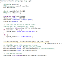
Void masterTaskFxn (UArg arg0, UArg arg1)
{
SPI_Handle masterSpi;
SPI_Transaction masterTransaction;
bool transferOK;
uint16_t aui16SpiTxBuffer[2];
SPI_Params stSpiParams;
SPI_Params_init(&stSpiParams);
stSpiParams.bitRate = 1500000;
stSpiParams.frameFormat = SPI_POL0_PHA1;
stSpiParams.dataSize = 16;
// Initialize SPI handle as default master
//masterSpi = SPI_open(Board_SPI1, NULL);
masterSpi = SPI_open(Board_SPI1, &stSpiParams);
if (masterSpi == NULL) {
System_abort("Error initializing SPI\n");
}
else {
System_printf("SPI initialized\n");
}
aui16SpiTxBuffer[0] = aui16SpiTxBuffer[0] | (HB_ENABLE << 0)
& (~(HB_CONFIG << 0));
// Initialize master SPI transaction structure
masterTransaction.count = 1;//16;//SPI_MSG_LENGTH;
masterTransaction.txBuf = aui16SpiTxBuffer[0];//(Ptr)masterTxBuffer;
masterTransaction.rxBuf = (Ptr)masterRxBuffer;
// Initiate SPI transfer
transferOK = SPI_transfer(masterSpi, &masterTransaction);
if(transferOK) {
// Print contents of master receive buffer
System_printf("Master: %s\n", masterRxBuffer);
}
else {
System_printf("Unsuccessful master SPI transfer");
}
// Deinitialize SPI
SPI_close(masterSpi);
System_printf("Done\n");
System_flush();
}
/*
* ======== main ========
*/
int main(void)
{
/* Construct BIOS objects */
Task_Params taskParams;
/* Call board init functions. */
Board_initGeneral();
Board_initGPIO();
Board_initSPI();
GPIOPinTypeGPIOOutput(GPIO_PORTP_BASE, GPIO_PIN_1);
GPIOPinTypeGPIOOutput(GPIO_PORTM_BASE, GPIO_PIN_5);
/* Construct master/slave Task threads */
Task_Params_init(&taskParams);
taskParams.priority = 1;
taskParams.stackSize = TASKSTACKSIZE;
taskParams.stack = &task0Stack;
Task_construct(&task0Struct, (Task_FuncPtr)masterTaskFxn, &taskParams, NULL);
/* taskParams.stack = &task1Stack;
taskParams.priority = 2;
Task_construct(&task1Struct, (Task_FuncPtr)slaveTaskFxn, &taskParams, NULL);*/
/*Task_Params_init(&taskParams);
taskParams.priority = 1;
taskParams.stackSize = TASKSTACKSIZE;
taskParams.stack = &task0Stack;
Task_construct(&task0Struct, (Task_FuncPtr)ioc_DefaultDOInit, &taskParams, NULL);*/
/* Turn on user LED */
GPIO_write(Board_LED0, Board_LED_ON);
//GPIO_write(BOARD_PORTM_PIN5, HIGH);
System_printf("Starting the SPI loop-back example\nSystem provider is set to"
" SysMin. Halt the target to view any SysMin contents in ROV.\n");
/* SysMin will only print to the console when you call flush or exit */
System_flush();
System_printf("This example requires external wires to be connected to the "
"header pins. Please see the Getting Started Guide for "
"details.\n");
/* SysMin will only print to the console when you call flush or exit */
System_flush();
/* Start BIOS */
BIOS_start();
return (0);
}
Hi Charles,
I've uploaded the two files.'spi_test_main.c' has the Task 'masterTaskFxn' to open, transfer and close the SPI bus.
'EK_TM4C1294XL.c' has 'EK_TM4C1294XL_initSPI' function to initialise the SSI3 bus peripheral.
The error comes 'Trouble Reading Memory Block at 0x4000b00c' while the same code is running in the spi loopback example. I just changed the SPI parameters.

Also, I'm unable to put breakpoints at any location. The following message comes if I do.

Hope you can help.
Best Regards,
Kiran
Hi,
Your spi_test_main.c contains code related to ioc which I'm not familiar with. I will suggest you isolate your problem by making minimal changes at a time. Start with the spiloopback.c example file as a starting point. Modify the file for SSI3 and run it before you add other features. This is the best way to troubleshoot your problem.
Hi Charles,
That is exactly what I did. I started with the example to run for SSI3 first.
Hi,
Can you revert your spi_test_main.c file to only include changes related to SSI3 and nothing else (e.g. ioc code)? Rerun it and if you can repeat the same error, please post the updated code.
