Part Number: TM4C1292NCPDT
Hello,
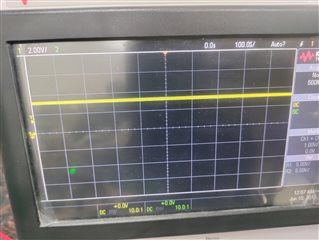
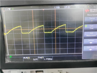
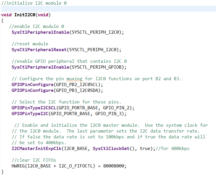
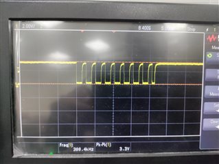
I'm giving an I2C signal from the uC and SCL and SDA are pulled up.
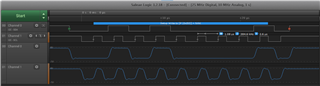
But when I check on scope, I see the SCL signal sometimes and unable to see it sometimes.
All the signals shorting, and connections are fine.
Please suggest what could be the reason behind this on and off thing.
Best regards,
Kiranjit