A related question is a question created from another question. When the related question is created, it will be automatically linked to the original question.
If you have a related question, please click the "Ask a related question" button in the top right corner. The newly created question will be automatically linked to this question.
TM4C129XNCZAD: USB Vbus hardware configuration for TM4C
4.3.1 USB Device Only For TM4C129x devices that are used in a device-only configuration, the only signal used in addition to USB0DM and USB0DP is USB0VBUS, which is located on port PB1. PB1 is 5-V tolerant. In USB deviceonly mode, USB0VBUS is used to detect when voltage has been applied to or removed from the USB connector, which triggers software to manage the internal USB PHY accordingly. For a USB device-only configuration, a 100Ω resistor should be placed in series between VBUS on the USB connector and PB1 (or alternate GPIO) on the microcontroller in order to limit damage caused by any ESD events.
For VBUS detection, it can be set by the TM4C's registers, adjusting the detection time? (timing forward or backward), or is this handled entirely by the TM4C hardware?
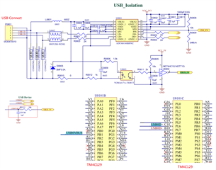
We found that if we add another capacitor to the VBUS to ground (the red block in the figure), after removing the USB cable and reconnecting it, the USB will not be able to connect and the TI TM4C USB device will not be visible in the windows device manager, We suspect that this capacitor (C0136) is the cause.
I have not see a need to use a cap. The only recommendation is 100ohm serious resistor on PB1 pin. Can you remove he cap and will it behave as expected?