This thread has been locked.

If you have a related question, please click the "Ask a related question" button in the top right corner. The newly created question will be automatically linked to this question.

TM4C123GH6PM: I2C Slave Mode Operation: Reading and Writing

Part Number: TM4C123GH6PM

Hello,

I would like to make my tm4c123 device, an i2c slave. I would like to read and write multiple bytes to different registers. Based on slave_receive_int.c I have devised the following:

void I2C0SlaveIntHandler(void) {

    // clear data interrupt
    HWREG(I2C0_BASE + I2C_O_SICR) = I2C_SICR_DATAIC;

    uint8_t startDetected = 0;
    uint8_t stopDetected = 0;

    if(HWREG(I2C0_BASE + I2C_O_SRIS) & I2C_SLAVE_INT_START) {
        startDetected = 1;
        HWREG(I2C0_BASE + I2C_O_SICR) = I2C_SICR_STARTIC;
    } else if(HWREG(I2C0_BASE + I2C_O_SRIS) & I2C_SLAVE_INT_STOP) {
        stopDetected = 1;
        HWREG(I2C0_BASE + I2C_O_SICR) = I2C_SICR_STOPIC;
    }

    switch(I2CSlaveStatus(I2C0_BASE) & (I2C_SCSR_TREQ | I2C_SCSR_RREQ)) {

        // data received
        case(I2C_SLAVE_ACT_RREQ):

            if(startDetected) { rxBufferIdx = 0; }

            if(I2CSlaveStatus(I2C0_BASE) & I2C_SCSR_FBR) {
                //currentState = SLAVE_RX;
            }

            rxBuffer[rxBufferIdx] = I2CSlaveDataGet(I2C0_BASE);
            rxBufferIdx++;

            break;

        // data requested
        case(I2C_SLAVE_ACT_TREQ):

            if(startDetected) { txBufferIdx = 0; }

            I2CSlaveDataPut(I2C0_BASE, txBuffer[txBufferIdx]);
            txBufferIdx++;

            break;


        default:
            break;
    }

    if(stopDetected/* && currentState == SLAVE_RX*/) {
    }

    g_i2c_ready = true;

}

And it is somewhat working, but not as expected.

I have the following questions:

1. is there an example that contains the state machine for a i2c slave device implemented in tm4c. in other devices like msp430 series, the i2c slave examples contain a fsm based handler for received data, them tm4c123 lacks such example. I googled, but I was not able to find an example.

2. how can i get the first byte? when the state is I2C_SLAVE_ACT_RREQ_FBR? when i2c write starts from master device, i would like to use the first byte as address, and then use the rest of the data to do different things.

3. how and where do we the first byte for read?

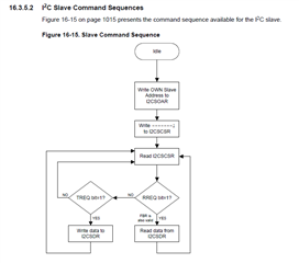
4. The interrupt handler is dealing with data, start, stop conditions/states. Are there any other states? On page 1015 of the datasheet, there is a "Figure 16-15. Slave Command Sequence" Is there a more detailed illustration of this?

Best Regards,

Can

  • Hi,

      There are various I2C flowcharts shown in the datasheet but most of them are for the master operations. There is one slave flowchart. Please see below or refer to the datasheet for details. Please expect delay as it is a public US holiday and I will be on vacation until Jan-2. Response will be delayed.

  • Hello Charles,

    I am aware of the slave flowchart. However it does not contain information on how to figure out start and end of a transaction, those interrupts are detected, but I was unable to understand whether it comes with byte transaction or seperately.

    Probably some testing and debugging, I will figure it out.

    Meanwhile could there be any helpers for different platforms that implements the i2c state machine? For example msp430s?

    Have a happy holiday,

    Best Regards,

    Can

  • Previously I had done an I2C slave using a msp430 and the code looked like below. Obviously it is not the same architecture, but i2c state machine should be similar since the protocol is the same. ~best regards

    #include <msp430.h>
    #include <stdint.h>
    #include <stdbool.h>

    #define SLAVE_ADDR 0x48

    #define CMD_CTRL_REG 0x01

    #define MAX_BUFFER_SIZE 32

    uint8_t CTRL_REG[2] = {0, 0};
    volatile uint16_t pwm = 0;

    typedef enum I2C_ModeEnum {
        IDLE_MODE,
        NACK_MODE,
        TX_REG_ADDRESS_MODE,
        RX_REG_ADDRESS_MODE,
        TX_DATA_MODE,
        RX_DATA_MODE,
        SWITCH_TO_RX_MODE,
        SWITHC_TO_TX_MODE,
        TIMEOUT_MODE
    } I2C_Mode;

    I2C_Mode SlaveMode = RX_REG_ADDRESS_MODE;
    uint8_t ReceiveRegAddr = 0;

    uint8_t ReceiveBuffer[MAX_BUFFER_SIZE] = {0};
    uint8_t RXByteCtr = 0;
    uint8_t ReceiveIndex = 0;
    uint8_t TransmitBuffer[MAX_BUFFER_SIZE] = {0};
    uint8_t TXByteCtr = 0;
    uint8_t TransmitIndex = 0;

    void I2C_Slave_ProcessCMD(uint8_t cmd);
    void I2C_Slave_TransactionDone(uint8_t cmd);
    void CopyArray(uint8_t *source, uint8_t *dest, uint8_t count);

    void I2C_Slave_ProcessCMD(uint8_t cmd) {

        ReceiveIndex = 0;
        TransmitIndex = 0;
        RXByteCtr = 0;
        TXByteCtr = 0;

        switch (cmd) {
            case (CMD_CTRL_REG):
                SlaveMode = RX_DATA_MODE;
                RXByteCtr = 2;
                UCB0IE &= ~UCTXIE;
                UCB0IE |= UCRXIE;
                break;
            default:
                __no_operation();
                break;
        }
    }

    void I2C_Slave_TransactionDone(uint8_t cmd) {
        switch (cmd) {
            case (CMD_CTRL_REG):
                CopyArray(ReceiveBuffer, CTRL_REG, 2);
                break;
            default:
                __no_operation();
                break;
        }
    }

    void CopyArray(uint8_t *source, uint8_t *dest, uint8_t count) {
        uint8_t copyIndex = 0;
        for (copyIndex = 0; copyIndex < count; copyIndex++) {
            dest[copyIndex] = source[copyIndex];
        }
    }

    void initGPIO() {

        // I2C pins
        P1SEL0 |= BIT2 | BIT3;
        P1SEL1 &= ~(BIT2 | BIT3);

        // PWM pin
        P2DIR |= BIT0;
        P2SEL0 |= BIT0;

        // LED
        P1OUT &= ~BIT0;
        P1DIR |= BIT0;

        // IN1 and IN2
        P6OUT &= ~BIT0 | BIT1;
        P6DIR |= BIT0 | BIT1;

        PM5CTL0 &= ~LOCKLPM5;

        TB1CCR0 = 1000-1;
        TB1CCTL1 = OUTMOD_7;
        TB1CCR1 = 0;

        TB1CTL = TBSSEL__SMCLK | MC__UP | TBCLR;

    }

    // P6OUT |= MODE_1;
    // P6OUT |= ~MODE_1; }

    void initI2C() {
        UCB0CTLW0 = UCSWRST;
        UCB0CTLW0 |= UCMODE_3 | UCSYNC;
        UCB0I2COA0 = SLAVE_ADDR | UCOAEN;
        UCB0CTLW0 &= ~UCSWRST;
        UCB0IE |= UCRXIE + UCSTPIE;
    }

    void initClockTo16MHz() {

        FRCTL0 = FRCTLPW | NWAITS_1;
        __bis_SR_register(SCG0);
        CSCTL3 |= SELREF__REFOCLK;
        CSCTL0 = 0;
        CSCTL1 &= ~(DCORSEL_7);
        CSCTL1 |= DCORSEL_5;
        CSCTL2 = FLLD_0 + 487;

        __delay_cycles(3);
        __bic_SR_register(SCG0);
        while(CSCTL7 & (FLLUNLOCK0 | FLLUNLOCK1));

        CSCTL4 = SELMS__DCOCLKDIV | SELA__REFOCLK;
    }

    int main(void) {

        WDTCTL = WDTPW | WDTHOLD;

        initClockTo16MHz();
        initGPIO();
        initI2C();

        bool in1 = false;
        bool in2 = false;

        while(1){

            __bis_SR_register(LPM3_bits + GIE);

            // flip led
            P1OUT ^= BIT0;

            // calculate and set pwm
            pwm = ((CTRL_REG[0] << 8) & 0x03) | CTRL_REG[1];
            TB1CCR1 = pwm;

            // calculate in1 and in2
            in1 = (CTRL_REG[0]) & 0x80 != 0;
            in2 = (CTRL_REG[0]) & 0x40 != 0;

            // switch in1 and in2
            if(in1) { P6OUT |= BIT0; } else { P6OUT |= ~BIT0; }
            if(in2) { P6OUT |= BIT1; } else { P6OUT |= ~BIT1; }

            // read en_diag

            // read cs? not here maybe do that with a timer interrupt?

        }

        return 0;
    }

    #pragma vector = USCI_B0_VECTOR
    __interrupt void USCI_B0_ISR(void) {

      uint8_t rx_val = 0;
      switch(__even_in_range(UCB0IV, USCI_I2C_UCBIT9IFG)) {
        case USCI_NONE:          break;
        case USCI_I2C_UCALIFG:   break;
        case USCI_I2C_UCNACKIFG:
          break;
        case USCI_I2C_UCSTTIFG:  break;
        case USCI_I2C_UCSTPIFG:
            UCB0IFG &= ~(UCTXIFG0);
            break;
        case USCI_I2C_UCRXIFG3:  break;
        case USCI_I2C_UCTXIFG3:  break;
        case USCI_I2C_UCRXIFG2:  break;
        case USCI_I2C_UCTXIFG2:  break;
        case USCI_I2C_UCRXIFG1:  break;
        case USCI_I2C_UCTXIFG1:  break;
        case USCI_I2C_UCRXIFG0:
            rx_val = UCB0RXBUF;
            switch (SlaveMode) {
              case (RX_REG_ADDRESS_MODE):
                  ReceiveRegAddr = rx_val;
                  I2C_Slave_ProcessCMD(ReceiveRegAddr);
                  break;
              case (RX_DATA_MODE):
                  ReceiveBuffer[ReceiveIndex++] = rx_val;
                  RXByteCtr--;
                  if(RXByteCtr == 0) {
                      SlaveMode = RX_REG_ADDRESS_MODE;
                      UCB0IE &= ~(UCTXIE);
                      UCB0IE |= UCRXIE;
                      I2C_Slave_TransactionDone(ReceiveRegAddr);
                  }
                  break;
              default:
                  __no_operation();
                  break;
            }
            break;
        case USCI_I2C_UCTXIFG0:
            switch (SlaveMode) {
              case (TX_DATA_MODE):
                  UCB0TXBUF = TransmitBuffer[TransmitIndex++];
                  TXByteCtr--;
                  if(TXByteCtr == 0) {
                      SlaveMode = RX_REG_ADDRESS_MODE;
                      UCB0IE &= ~(UCTXIE);
                      UCB0IE |= UCRXIE;
                      I2C_Slave_TransactionDone(ReceiveRegAddr);
                  }
                  break;
              default:
                  __no_operation();
                  break;
            }
            break;
        default: break;
      }
      __bic_SR_register_on_exit(LPM3_bits);
    }

  • Hi Can,

      Sorry, I just got back from the vacation. Do you still need assistance on this thread? Although not the same I2C, I find the I2C flowcharts for both master and slave operations for C6000 and Hercules devices. https://www.ti.com/lit/pdf/spru175

  • Hello Charles, yes, I have a i2c device operating in slave mode perfectly. thank you.