This thread has been locked.

If you have a related question, please click the "Ask a related question" button in the top right corner. The newly created question will be automatically linked to this question.

AM2634: Why are Timer instance choices limited?

Part Number: AM2634
Other Parts Discussed in Thread: TMDSCNCD263, SYSCONFIG

To expert

I am currently conducting pre-development using "TMDSCNCD263".

In order to use multi-core, we created projects that are used in each core based on the example.

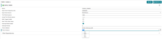
However, depending on the project, not all Timer instances are selected.

what's the reason?

1. Project for R5SS0_0 : Cannot select RTI0 from Timer instance

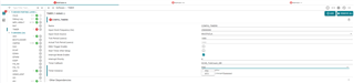
2.  Project for R5SS1_0 : Cannot select RTI2 from Timer instance

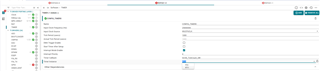
3.  Project for R5SS1_1 : Cannot select RTI3 from Timer instance

4. When the System project is opened together : In all projects, it is impossible to select anything other than RTI1 and conflicts occur

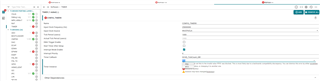
Could you please let me know if there is any way to solve this?

Best Regards

Jiung Choi

  • Hello Jiung Choi,

    We have received your question and are looking into this now. Please allow a few days for follow up.

    Best Regards,

    Zackary Fleenor

  • In the mean-time, can you please provide project files mentioned in the thread?

  • In the meantime, can you please provide project files mentioned in the thread?

  • Hi, Zackary Fleenor

    Unfortunately, file uploads are restricted due to internal security policies.

    Therefore, the text of the sysconfig files is delivered as follows.

    If you tell us the file you need to check, I can provide it in text format.

    Best Regards

    Jiung Choi

  • Hello Jiung Choi,

    The SysConfig text file will be useful.

    I wanted to draw attention to the following three bolded points. These details are provided in the MCU+SDK Driver Porting Layer (DPL) - Clock documentation (link provided below).

    • The user specific callback can be called in interrupt, SWI or task context depending on the underlying RTOS that is used
      • In no-RTOS case, the callback is called in interrupt context
      • It is recommended to assume that the callback is called in ISR context and not block within the callback.
      • Typically one should do very limited work within the callback itself and defer the larger part of the work to a task via a semaphore post.
    • ClockP_usleep and ClockP_sleep will block until the user specified time is expired.
      • In no-RTOS case, there is only a single main task and that will block or spin until the ticks have elasped
      • In RTOS case, the current executing task will 'pend' and schedular will switch to another ready task
      • In both cases ISR's are still active
      • In RTOS case, actual sleep will be in the range of sleep time - ClockP_ticksToUsec(1) to sleep time. If you need to guarantee atleast minimum sleep of sleep time, you need to sleep for sleep time + ClockP_ticksToUsec(1), i.e there will be a error on 1 OS tick at max.
    • When using multiple CPUs, make sure each CPU uses a different HW timer else the tick ISR will not trigger as expected.
    • Recommended value of tick period is 1ms or 1000us
    • Adding any module in SysConfig, automatically adds a clock module with a timer configured for 1ms. The default timer is chosen such that it does not overlap with a timer from another CPU.
    • In M4F, the M4F internal SysTick timer is used.
    • In R5F, one of the many SOC level timer is used.

    https://software-dl.ti.com/mcu-plus-sdk/esd/AM263X/latest/exports/docs/api_guide_am263x/KERNEL_DPL_CLOCK_PAGE.html#:~:text=NA-,Important%20Usage%20Guidelines,-The%20user%20specific

    I am looping in our software experts for additional feedback into possible limitations with multi-core applications.

    Best Regards,

    Zackary Fleenor

  • Hi, Zackary Fleenor

    I understood that in multi-core I need to use a different timer instance for each core.

    But the problem now is that I can't select the timer instance.

    The sysconfig file I'm using is:

    1. System Project

    <?xml version="1.0" encoding="UTF-8" standalone="no"?>
    <system>
    <project configuration="@match" id="project_0" name="empty_am263x-cc_r5fss0-0_nortos_ti-arm-clang"/>
    <core id="MAIN_PULSAR_Cortex_R5_0_0" project="project_0"/>
    <project configuration="@match" id="project_1" name="empty_am263x-cc_r5fss0-1_nortos_ti-arm-clang"/>
    <core id="MAIN_PULSAR_Cortex_R5_0_1" project="project_1"/>
    <project configuration="@match" id="project_1" name="empty_am263x-cc_r5fss1-0_nortos_ti-arm-clang"/>
    <core id="MAIN_PULSAR_Cortex_R5_1_0" project="project_2"/>
    <project configuration="@match" id="project_1" name="empty_am263x-cc_r5fss1-1_nortos_ti-arm-clang"/>
    <core id="MAIN_PULSAR_Cortex_R5_1_1" project="project_3"/>
    <preBuildSteps/>
    <postBuildSteps>
    <step command="$(MAKE) -C ${CCS_PROJECT_DIR} -f makefile_system_ccs_bootimage_gen OUTNAME=empty_system PROFILE=${ConfigName} MCU_PLUS_SDK_PATH=${MCU_PLUS_SDK_PATH} CG_TOOL_ROOT=${CG_TOOL_ROOT} CCS_INSTALL_DIR=${CCS_INSTALL_DIR} CCS_IDE_MODE=${CCS_IDE_MODE}"/>
    </postBuildSteps>
    <project configuration="Debug" id="project_1014004847" name="LGIT_Application_R5FSS0"/>
    <core id="Cortex_R5_0" project="project_1014004847"/>
    <project configuration="Debug" id="project_1459515963" name="LGIT_Application_R5FSS1_0"/>
    <core id="Cortex_R5_2" project="project_1459515963"/>
    <project configuration="Debug" id="project_1975321599" name="LGIT_Application_R5FSS1_1"/>
    <core id="Cortex_R5_3" project="project_1975321599"/>
    </system>

    2. R5FSS0 Project

    /**
    * These arguments were used when this file was generated. They will be automatically applied on subsequent loads
    * via the GUI or CLI. Run CLI with '--help' for additional information on how to override these arguments.
    * @cliArgs --device "AM263x_beta" --package "ZCZ" --part "AM263x" --context "r5fss0-0" --product "MCU_PLUS_SDK_AM263x@08.05.00"
    * @versions {"tool":"1.14.0+2667"}
    */
    scripting.excludeFromBuild("ti_enet_config.c");
    scripting.excludeFromBuild("ti_enet_config.h");
    scripting.excludeFromBuild("ti_enet_open_close.c");
    scripting.excludeFromBuild("ti_enet_open_close.h");

    /**
    * Import the modules used in this configuration.
    */
    const adc = scripting.addModule("/drivers/adc/adc", {}, false);
    const adc1 = adc.addInstance();
    const cmpss = scripting.addModule("/drivers/cmpss/cmpss", {}, false);
    const cmpss1 = cmpss.addInstance();
    const gpio = scripting.addModule("/drivers/gpio/gpio", {}, false);
    const gpio1 = gpio.addInstance();
    const ipc = scripting.addModule("/drivers/ipc/ipc");
    const mcan = scripting.addModule("/drivers/mcan/mcan", {}, false);
    const mcan1 = mcan.addInstance();
    const clock = scripting.addModule("/kernel/dpl/clock");
    const debug_log = scripting.addModule("/kernel/dpl/debug_log");
    const mpu_armv7 = scripting.addModule("/kernel/dpl/mpu_armv7", {}, false);
    const mpu_armv71 = mpu_armv7.addInstance();
    const mpu_armv72 = mpu_armv7.addInstance();
    const mpu_armv73 = mpu_armv7.addInstance();
    const mpu_armv74 = mpu_armv7.addInstance();
    const mpu_armv75 = mpu_armv7.addInstance();
    const mpu_armv76 = mpu_armv7.addInstance();
    const timer = scripting.addModule("/kernel/dpl/timer", {}, false);
    const timer1 = timer.addInstance();
    const int_xbar = scripting.addModule("/xbar/int_xbar/int_xbar", {}, false);
    const int_xbar1 = int_xbar.addInstance();
    const output_xbar = scripting.addModule("/xbar/output_xbar/output_xbar", {}, false);
    const output_xbar1 = output_xbar.addInstance();

    /**
    * Write custom configuration values to the imported modules.
    */
    adc1.$name = "CONFIG_ADC0";
    adc1.interruptPulseMode = "ADC_PULSE_END_OF_CONV";
    adc1.enableInterrupt1 = true;
    adc1.soc2Trigger = "ADC_TRIGGER_EPWM0_SOCA";
    adc1.enableConverter = true;
    adc1.soc2Channel = "ADC_CH_ADCIN2";
    adc1.ADC.$assign = "ADC0";
    adc1.ADC.AIN0.$assign = "ball.V15";
    adc1.ADC.AIN0.$used = false;
    adc1.ADC.AIN1.$used = false;
    adc1.ADC.AIN2.$used = false;
    adc1.ADC.AIN3.$used = false;
    adc1.ADC.AIN4.$used = false;
    adc1.ADC.AIN5.$used = false;

    cmpss1.$name = "CONFIG_CMPSS0";
    cmpss1.cmpssBase = "CSL_CONTROLSS_CMPSSA1_U_BASE";
    cmpss1.enableModule = true;
    cmpss1.dacValHigh = 2048;
    cmpss1.dacRefVoltage = "CMPSS_DACREF_VDAC";
    cmpss1.initFilterHigh = true;
    cmpss1.clearFilterLatchHigh = true;
    cmpss1.configLatchHigh = true;
    cmpss1.highCTRIPOUT = "CMPSS_TRIPOUT_LATCH";
    cmpss1.highCTRIP = "CMPSS_TRIP_LATCH";

    gpio1.$name = "CONFIG_GPIO22";
    gpio1.pinDir = "OUTPUT";
    gpio1.GPIO.gpioPin.$assign = "ball.A8";

    ipc.r5fss0_1 = "NONE";
    ipc.r5fss1_0 = "notify";
    ipc.r5fss1_1 = "notify";

    mcan1.$name = "CONFIG_MCAN1";
    mcan1.MCAN.$assign = "MCAN1";
    mcan1.MCAN.RX.$assign = "ball.L2";
    mcan1.MCAN.TX.$assign = "ball.K1";

    debug_log.enableCssLog = false;
    debug_log.enableLogZoneWarning = false;
    debug_log.enableLogZoneError = false;

    mpu_armv71.$name = "CONFIG_MPU_REGION0";
    mpu_armv71.size = 31;
    mpu_armv71.attributes = "Device";
    mpu_armv71.accessPermissions = "Supervisor RD+WR, User RD";
    mpu_armv71.allowExecute = false;

    mpu_armv72.$name = "CONFIG_MPU_REGION1";
    mpu_armv72.size = 15;
    mpu_armv72.accessPermissions = "Supervisor RD+WR, User RD";

    mpu_armv73.$name = "CONFIG_MPU_REGION2";
    mpu_armv73.baseAddr = 0x80000;
    mpu_armv73.size = 15;
    mpu_armv73.accessPermissions = "Supervisor RD+WR, User RD";

    mpu_armv74.$name = "CONFIG_MPU_REGION3";
    mpu_armv74.accessPermissions = "Supervisor RD+WR, User RD";
    mpu_armv74.baseAddr = 0x70000000;
    mpu_armv74.size = 21;
    mpu_armv74.attributes = "NonCached";

    mpu_armv75.$name = "CONFIG_MPU_REGION4";
    mpu_armv75.baseAddr = 0x50D00000;
    mpu_armv75.size = 14;
    mpu_armv75.allowExecute = false;
    mpu_armv75.attributes = "Device";

    mpu_armv76.$name = "CONFIG_MPU_REGION5";
    mpu_armv76.baseAddr = 0x72000000;
    mpu_armv76.size = 14;
    mpu_armv76.allowExecute = false;
    mpu_armv76.attributes = "NonCached";

    timer1.$name = "CONFIG_TIMER0";
    timer1.timerCallback = "SCHD_TickCount_ISR";

    int_xbar1.$name = "CONFIG_INT_XBAR1";
    int_xbar1.xbarOutput = ["ADC0_INT1"];

    output_xbar1.$name = "CONFIG_OUTPUT_XBAR0";
    output_xbar1.xbarOutput = ["CMPSSA1_CTRIPH"];
    output_xbar1.OUTPUTXBAR.$assign = "OUTPUTXBAR0";

    /**
    * Pinmux solution for unlocked pins/peripherals. This ensures that minor changes to the automatic solver in a future
    * version of the tool will not impact the pinmux you originally saw. These lines can be completely deleted in order to
    * re-solve from scratch.
    */
    gpio1.GPIO.$suggestSolution = "GPIO0";
    timer1.RTI.$suggestSolution = "RTI1";
    output_xbar1.OUTPUTXBAR.OUTPUTXBAR.$suggestSolution = "ball.R3";

    3. R5FSS1_0 Project

    /**
    * These arguments were used when this file was generated. They will be automatically applied on subsequent loads
    * via the GUI or CLI. Run CLI with '--help' for additional information on how to override these arguments.
    * @cliArgs --device "AM263x_beta" --package "ZCZ" --part "AM263x" --context "r5fss1-0" --product "MCU_PLUS_SDK_AM263x@08.05.00"
    * @versions {"tool":"1.14.0+2667"}
    */
    scripting.excludeFromBuild("ti_enet_config.c");
    scripting.excludeFromBuild("ti_enet_config.h");
    scripting.excludeFromBuild("ti_enet_open_close.c");
    scripting.excludeFromBuild("ti_enet_open_close.h");

    /**
    * Import the modules used in this configuration.
    */
    const adc = scripting.addModule("/drivers/adc/adc", {}, false);
    const adc1 = adc.addInstance();
    const cmpss = scripting.addModule("/drivers/cmpss/cmpss", {}, false);
    const cmpss1 = cmpss.addInstance();
    const epwm = scripting.addModule("/drivers/epwm/epwm", {}, false);
    const epwm1 = epwm.addInstance();
    const epwm2 = epwm.addInstance();
    const epwm3 = epwm.addInstance();
    const epwm4 = epwm.addInstance();
    const gpio = scripting.addModule("/drivers/gpio/gpio", {}, false);
    const gpio1 = gpio.addInstance();
    const ipc = scripting.addModule("/drivers/ipc/ipc");
    const clock = scripting.addModule("/kernel/dpl/clock");
    const debug_log = scripting.addModule("/kernel/dpl/debug_log");
    const mpu_armv7 = scripting.addModule("/kernel/dpl/mpu_armv7", {}, false);
    const mpu_armv71 = mpu_armv7.addInstance();
    const mpu_armv72 = mpu_armv7.addInstance();
    const mpu_armv73 = mpu_armv7.addInstance();
    const mpu_armv74 = mpu_armv7.addInstance();
    const mpu_armv75 = mpu_armv7.addInstance();
    const mpu_armv76 = mpu_armv7.addInstance();
    const timer = scripting.addModule("/kernel/dpl/timer", {}, false);
    const timer1 = timer.addInstance();
    const epwm_xbar = scripting.addModule("/xbar/epwm_xbar/epwm_xbar", {}, false);
    const epwm_xbar1 = epwm_xbar.addInstance();
    const int_xbar = scripting.addModule("/xbar/int_xbar/int_xbar", {}, false);
    const int_xbar1 = int_xbar.addInstance();
    const output_xbar = scripting.addModule("/xbar/output_xbar/output_xbar", {}, false);
    const output_xbar1 = output_xbar.addInstance();

    /**
    * Write custom configuration values to the imported modules.
    */
    adc1.interruptPulseMode = "ADC_PULSE_END_OF_CONV";
    adc1.enableConverter = true;
    adc1.soc2Channel = "ADC_CH_ADCIN2";
    adc1.$name = "CONFIG_ADC1";
    adc1.enableInterrupt1 = true;
    adc1.soc2Trigger = "ADC_TRIGGER_EPWM0_SOCA";
    adc1.interrupt1SOCSource = "ADC_SOC_NUMBER2";
    adc1.ADC.$assign = "ADC1";
    adc1.ADC.AIN0.$used = false;
    adc1.ADC.AIN1.$used = false;
    adc1.ADC.AIN2.$assign = "ball.T12";
    adc1.ADC.AIN3.$used = false;
    adc1.ADC.AIN4.$used = false;
    adc1.ADC.AIN5.$used = false;

    cmpss1.dacRefVoltage = "CMPSS_DACREF_VDAC";
    cmpss1.initFilterHigh = true;
    cmpss1.clearFilterLatchHigh = true;
    cmpss1.configLatchHigh = true;
    cmpss1.highCTRIPOUT = "CMPSS_TRIPOUT_LATCH";
    cmpss1.highCTRIP = "CMPSS_TRIP_LATCH";
    cmpss1.enableBlanking = true;
    cmpss1.dacValLoad = "CMPSS_DACVAL_PWMSYNC";
    cmpss1.latchResetHigh = true;
    cmpss1.enableModule = true;
    cmpss1.dacValSource = "CMPSS_DACSRC_RAMP";
    cmpss1.dacValHigh = 4095;
    cmpss1.maxRampVal = 65535;
    cmpss1.ramDecVal = 1;
    cmpss1.cmpssBase = "CSL_CONTROLSS_CMPSSA3_U_BASE";
    cmpss1.$name = "CONFIG_CMPSS3";

    epwm1.$name = "CONFIG_EPWM0";
    epwm1.epwmEventTrigger_EPWM_SOC_A_triggerEnable = true;
    epwm1.epwmEventTrigger_EPWM_SOC_A_triggerSource = "EPWM_SOC_TBCTR_ZERO";
    epwm1.epwmEventTrigger_EPWM_SOC_A_triggerEventPrescalar = "1";
    epwm1.epwmDigitalCompare_EPWM_DC_TYPE_DCAH_combinationInputConfig = ["EPWM_DC_COMBINATIONAL_TRIPIN1"];
    epwm1.epwmDigitalCompare_EPWM_DC_TYPE_DCBH_combinationInputConfig = ["EPWM_DC_COMBINATIONAL_TRIPIN1"];
    epwm1.epwmGroup = "EPWM_GROUP2";
    epwm1.epwmDigitalCompare_useBlankingWindow = true;
    epwm1.epwmDigitalCompare_blankingWindowEvent = "EPWM_DC_WINDOW_START_TBCTR_ZERO";
    epwm1.epwmTimebase_counterMode = "EPWM_COUNTER_MODE_UP";
    epwm1.epwmActionQualifier_EPWM_AQ_OUTPUT_A_ON_TIMEBASE_ZERO = "EPWM_AQ_OUTPUT_HIGH";
    epwm1.epwmActionQualifier_EPWM_AQ_OUTPUT_A_ON_TIMEBASE_PERIOD = "EPWM_AQ_OUTPUT_LOW";
    epwm1.epwmActionQualifier_EPWM_AQ_OUTPUT_A_ON_TIMEBASE_UP_CMPA = "EPWM_AQ_OUTPUT_LOW";
    epwm1.epwmTimebase_period = 1000;
    epwm1.epwmDigitalCompare_EPWM_DC_MODULE_B_EPWM_DC_EVENT_2_eventSync = "EPWM_DC_EVENT_INPUT_NOT_SYNCED";
    epwm1.epwmDeadband_polarityFED = "EPWM_DB_POLARITY_ACTIVE_LOW";
    epwm1.epwmActionQualifier_EPWM_AQ_OUTPUT_A_ON_T1_COUNT_UP = "EPWM_AQ_OUTPUT_LOW";
    epwm1.epwmDigitalCompare_EPWM_TZ_DC_OUTPUT_A1 = "EPWM_TZ_EVENT_DCXH_HIGH";
    epwm1.hrpwm_tbprdHR = 128;
    epwm1.hrpwm_syncSource = "HRPWM_PWMSYNC_SOURCE_ZERO";
    epwm1.epwmDeadband_enableRED = true;
    epwm1.epwmDeadband_enableFED = true;
    epwm1.epwmDeadband_delayFED = 20;
    epwm1.epwmTimebase_phaseEnable = true;
    epwm1.epwmTimebase_emulationMode = "EPWM_EMULATION_STOP_AFTER_FULL_CYCLE";
    epwm1.epwmTimebase_syncOutPulseMode = ["EPWM_SYNC_OUT_PULSE_ON_CNTR_ZERO"];
    epwm1.epwmDeadband_delayRED = 20;
    epwm1.epwmTripZone_EPWM_TZ_ACTION_EVENT_TZA = "EPWM_TZ_ACTION_DISABLE";
    epwm1.epwmTripZone_EPWM_TZ_ACTION_EVENT_TZB = "EPWM_TZ_ACTION_DISABLE";
    epwm1.epwmTripZone_EPWM_TZ_ACTION_EVENT_DCAEVT1 = "EPWM_TZ_ACTION_DISABLE";
    epwm1.epwmTripZone_EPWM_TZ_ACTION_EVENT_DCAEVT2 = "EPWM_TZ_ACTION_DISABLE";
    epwm1.epwmTripZone_EPWM_TZ_ACTION_EVENT_DCBEVT1 = "EPWM_TZ_ACTION_DISABLE";
    epwm1.epwmTripZone_EPWM_TZ_ACTION_EVENT_DCBEVT2 = "EPWM_TZ_ACTION_DISABLE";
    epwm1.epwmDigitalCompare_blankingWindowLength = 2;
    epwm1.epwmDigitalCompare_EPWM_DC_MODULE_A_EPWM_DC_EVENT_2_eventSync = "EPWM_DC_EVENT_INPUT_NOT_SYNCED";
    epwm1.EPWM.$assign = "EPWM0";
    epwm1.EPWM.A.$assign = "ball.B2";
    epwm1.EPWM.B.$assign = "ball.B1";

    epwm2.$name = "CONFIG_EPWM1";
    epwm2.epwmTimebase_syncOutPulseMode = ["EPWM_SYNC_OUT_PULSE_ON_SOFTWARE"];
    epwm2.epwmTimebase_emulationMode = "EPWM_EMULATION_STOP_AFTER_FULL_CYCLE";
    epwm2.epwmDeadband_enableRED = true;
    epwm2.epwmGroup = "EPWM_GROUP2";
    epwm2.epwmTimebase_counterMode = "EPWM_COUNTER_MODE_UP";
    epwm2.epwmActionQualifier_EPWM_AQ_OUTPUT_A_ON_TIMEBASE_ZERO = "EPWM_AQ_OUTPUT_HIGH";
    epwm2.epwmActionQualifier_EPWM_AQ_OUTPUT_A_ON_TIMEBASE_PERIOD = "EPWM_AQ_OUTPUT_LOW";
    epwm2.epwmActionQualifier_EPWM_AQ_OUTPUT_A_ON_TIMEBASE_UP_CMPA = "EPWM_AQ_OUTPUT_LOW";
    epwm2.epwmTimebase_period = 1000;
    epwm2.epwmTimebase_phaseEnable = true;
    epwm2.epwmDeadband_delayRED = 8;
    epwm2.epwmTimebase_syncInPulseSource = "EPWM_SYNC_IN_PULSE_SRC_SYNCOUT_EPWM0";
    epwm2.epwmTimebase_phaseShift = 2;
    epwm2.epwmDeadband_enableFED = true;
    epwm2.epwmDeadband_inputFED = "EPWM_DB_INPUT_DB_RED";
    epwm2.epwmDeadband_delayFED = 12;
    epwm2.epwmDeadband_outputSwapOutA = true;
    epwm2.epwmDeadband_outputSwapOutB = true;
    epwm2.epwmDigitalCompare_EPWM_DC_TYPE_DCAH_combinationInputConfig = ["EPWM_DC_COMBINATIONAL_TRIPIN1"];
    epwm2.epwmTripZone_EPWM_TZ_ACTION_EVENT_TZA = "EPWM_TZ_ACTION_DISABLE";
    epwm2.epwmTripZone_EPWM_TZ_ACTION_EVENT_TZB = "EPWM_TZ_ACTION_DISABLE";
    epwm2.epwmTripZone_EPWM_TZ_ACTION_EVENT_DCAEVT1 = "EPWM_TZ_ACTION_DISABLE";
    epwm2.epwmTripZone_EPWM_TZ_ACTION_EVENT_DCAEVT2 = "EPWM_TZ_ACTION_DISABLE";
    epwm2.epwmTripZone_EPWM_TZ_ACTION_EVENT_DCBEVT1 = "EPWM_TZ_ACTION_DISABLE";
    epwm2.epwmTripZone_EPWM_TZ_ACTION_EVENT_DCBEVT2 = "EPWM_TZ_ACTION_DISABLE";
    epwm2.epwmDigitalCompare_EPWM_TZ_DC_OUTPUT_A1 = "EPWM_TZ_EVENT_DCXH_HIGH";
    epwm2.epwmDigitalCompare_EPWM_DC_MODULE_A_EPWM_DC_EVENT_2_eventSync = "EPWM_DC_EVENT_INPUT_NOT_SYNCED";
    epwm2.epwmActionQualifier_EPWM_AQ_OUTPUT_A_ON_T1_COUNT_UP = "EPWM_AQ_OUTPUT_LOW";
    epwm2.epwmDigitalCompare_useBlankingWindow = true;
    epwm2.epwmDigitalCompare_blankingWindowEvent = "EPWM_DC_WINDOW_START_TBCTR_ZERO";
    epwm2.epwmDigitalCompare_blankingWindowLength = 2;
    epwm2.EPWM.$assign = "EPWM1";
    epwm2.EPWM.A.$assign = "ball.D3";
    epwm2.EPWM.B.$used = false;

    epwm3.$name = "CONFIG_EPWM2";
    epwm3.epwmTimebase_syncOutPulseMode = ["EPWM_SYNC_OUT_PULSE_ON_SOFTWARE"];
    epwm3.epwmTimebase_phaseEnable = true;
    epwm3.epwmTimebase_emulationMode = "EPWM_EMULATION_STOP_AFTER_FULL_CYCLE";
    epwm3.epwmGroup = "EPWM_GROUP2";
    epwm3.epwmTimebase_counterMode = "EPWM_COUNTER_MODE_UP";
    epwm3.epwmActionQualifier_EPWM_AQ_OUTPUT_A_ON_TIMEBASE_ZERO = "EPWM_AQ_OUTPUT_HIGH";
    epwm3.epwmActionQualifier_EPWM_AQ_OUTPUT_A_ON_TIMEBASE_PERIOD = "EPWM_AQ_OUTPUT_LOW";
    epwm3.epwmActionQualifier_EPWM_AQ_OUTPUT_A_ON_TIMEBASE_UP_CMPA = "EPWM_AQ_OUTPUT_LOW";
    epwm3.epwmTimebase_period = 1000;
    epwm3.epwmDeadband_enableRED = true;
    epwm3.epwmDeadband_delayRED = 12;
    epwm3.epwmTimebase_syncInPulseSource = "EPWM_SYNC_IN_PULSE_SRC_SYNCOUT_EPWM0";
    epwm3.epwmTimebase_phaseShift = 2;
    epwm3.epwmDeadband_enableFED = true;
    epwm3.epwmDeadband_delayFED = 8;
    epwm3.epwmDeadband_inputFED = "EPWM_DB_INPUT_DB_RED";
    epwm3.epwmDeadband_outputSwapOutA = true;
    epwm3.epwmDeadband_outputSwapOutB = true;
    epwm3.epwmDeadband_polarityFED = "EPWM_DB_POLARITY_ACTIVE_LOW";
    epwm3.epwmActionQualifier_EPWM_AQ_OUTPUT_A_ON_T1_COUNT_UP = "EPWM_AQ_OUTPUT_LOW";
    epwm3.epwmTripZone_EPWM_TZ_ACTION_EVENT_TZA = "EPWM_TZ_ACTION_DISABLE";
    epwm3.epwmTripZone_EPWM_TZ_ACTION_EVENT_TZB = "EPWM_TZ_ACTION_DISABLE";
    epwm3.epwmTripZone_EPWM_TZ_ACTION_EVENT_DCAEVT1 = "EPWM_TZ_ACTION_DISABLE";
    epwm3.epwmTripZone_EPWM_TZ_ACTION_EVENT_DCAEVT2 = "EPWM_TZ_ACTION_DISABLE";
    epwm3.epwmTripZone_EPWM_TZ_ACTION_EVENT_DCBEVT1 = "EPWM_TZ_ACTION_DISABLE";
    epwm3.epwmTripZone_EPWM_TZ_ACTION_EVENT_DCBEVT2 = "EPWM_TZ_ACTION_DISABLE";
    epwm3.epwmDigitalCompare_EPWM_TZ_DC_OUTPUT_A1 = "EPWM_TZ_EVENT_DCXH_HIGH";
    epwm3.epwmDigitalCompare_EPWM_DC_TYPE_DCAH_combinationInputConfig = ["EPWM_DC_COMBINATIONAL_TRIPIN1"];
    epwm3.epwmDigitalCompare_EPWM_DC_MODULE_A_EPWM_DC_EVENT_2_eventSync = "EPWM_DC_EVENT_INPUT_NOT_SYNCED";
    epwm3.epwmDigitalCompare_useBlankingWindow = true;
    epwm3.epwmDigitalCompare_blankingWindowEvent = "EPWM_DC_WINDOW_START_TBCTR_ZERO";
    epwm3.epwmDigitalCompare_blankingWindowLength = 2;
    epwm3.EPWM.$assign = "EPWM2";
    epwm3.EPWM.A.$assign = "ball.C2";
    epwm3.EPWM.B.$used = false;

    epwm4.$name = "CONFIG_EPWM3";
    epwm4.epwmGroup = "EPWM_GROUP2";
    epwm4.epwmTimebase_emulationMode = "EPWM_EMULATION_STOP_AFTER_FULL_CYCLE";
    epwm4.epwmTimebase_period = 1000;
    epwm4.epwmTimebase_counterMode = "EPWM_COUNTER_MODE_UP";
    epwm4.epwmTimebase_phaseEnable = true;
    epwm4.epwmTimebase_syncOutPulseMode = ["EPWM_SYNC_OUT_PULSE_ON_SOFTWARE"];
    epwm4.epwmDeadband_enableRED = true;
    epwm4.epwmActionQualifier_EPWM_AQ_OUTPUT_A_ON_TIMEBASE_ZERO = "EPWM_AQ_OUTPUT_HIGH";
    epwm4.epwmActionQualifier_EPWM_AQ_OUTPUT_A_ON_TIMEBASE_PERIOD = "EPWM_AQ_OUTPUT_LOW";
    epwm4.epwmActionQualifier_EPWM_AQ_OUTPUT_A_ON_TIMEBASE_UP_CMPA = "EPWM_AQ_OUTPUT_LOW";
    epwm4.epwmDeadband_delayRED = 12;
    epwm4.epwmTimebase_syncInPulseSource = "EPWM_SYNC_IN_PULSE_SRC_SYNCOUT_EPWM0";
    epwm4.epwmTimebase_phaseShift = 2;
    epwm4.epwmDeadband_enableFED = true;
    epwm4.epwmDeadband_delayFED = 8;
    epwm4.epwmDeadband_inputFED = "EPWM_DB_INPUT_DB_RED";
    epwm4.epwmDeadband_outputSwapOutA = true;
    epwm4.epwmDeadband_outputSwapOutB = true;
    epwm4.epwmDeadband_polarityFED = "EPWM_DB_POLARITY_ACTIVE_LOW";
    epwm4.epwmActionQualifier_EPWM_AQ_OUTPUT_A_ON_T1_COUNT_UP = "EPWM_AQ_OUTPUT_LOW";
    epwm4.epwmTripZone_EPWM_TZ_ACTION_EVENT_TZA = "EPWM_TZ_ACTION_DISABLE";
    epwm4.epwmTripZone_EPWM_TZ_ACTION_EVENT_TZB = "EPWM_TZ_ACTION_DISABLE";
    epwm4.epwmTripZone_EPWM_TZ_ACTION_EVENT_DCAEVT1 = "EPWM_TZ_ACTION_DISABLE";
    epwm4.epwmTripZone_EPWM_TZ_ACTION_EVENT_DCAEVT2 = "EPWM_TZ_ACTION_DISABLE";
    epwm4.epwmTripZone_EPWM_TZ_ACTION_EVENT_DCBEVT1 = "EPWM_TZ_ACTION_DISABLE";
    epwm4.epwmTripZone_EPWM_TZ_ACTION_EVENT_DCBEVT2 = "EPWM_TZ_ACTION_DISABLE";
    epwm4.epwmDigitalCompare_EPWM_DC_TYPE_DCAH_combinationInputConfig = ["EPWM_DC_COMBINATIONAL_TRIPIN1"];
    epwm4.epwmDigitalCompare_EPWM_TZ_DC_OUTPUT_A1 = "EPWM_TZ_EVENT_DCXH_HIGH";
    epwm4.epwmDigitalCompare_EPWM_DC_MODULE_A_EPWM_DC_EVENT_2_eventSync = "EPWM_DC_EVENT_INPUT_NOT_SYNCED";
    epwm4.epwmDigitalCompare_useBlankingWindow = true;
    epwm4.epwmDigitalCompare_blankingWindowEvent = "EPWM_DC_WINDOW_START_TBCTR_ZERO";
    epwm4.epwmDigitalCompare_blankingWindowLength = 2;
    epwm4.EPWM.$assign = "EPWM3";
    epwm4.EPWM.A.$assign = "ball.E2";
    epwm4.EPWM.B.$used = false;

    gpio1.$name = "CONFIG_GPIO22";
    gpio1.pinDir = "OUTPUT";
    gpio1.GPIO.gpioPin.$assign = "ball.A8";

    ipc.r5fss0_0 = "notify";
    ipc.r5fss0_1 = "NONE";
    ipc.r5fss1_1 = "NONE";

    debug_log.enableLogZoneError = false;
    debug_log.enableLogZoneWarning = false;
    debug_log.enableCssLog = false;

    mpu_armv71.$name = "CONFIG_MPU_REGION0";
    mpu_armv71.size = 31;
    mpu_armv71.attributes = "Device";
    mpu_armv71.accessPermissions = "Supervisor RD+WR, User RD";
    mpu_armv71.allowExecute = false;

    mpu_armv72.$name = "CONFIG_MPU_REGION1";
    mpu_armv72.size = 15;
    mpu_armv72.accessPermissions = "Supervisor RD+WR, User RD";

    mpu_armv73.$name = "CONFIG_MPU_REGION2";
    mpu_armv73.baseAddr = 0x80000;
    mpu_armv73.size = 15;
    mpu_armv73.accessPermissions = "Supervisor RD+WR, User RD";

    mpu_armv74.$name = "CONFIG_MPU_REGION3";
    mpu_armv74.accessPermissions = "Supervisor RD+WR, User RD";
    mpu_armv74.baseAddr = 0x70000000;
    mpu_armv74.size = 21;
    mpu_armv74.attributes = "NonCached";

    mpu_armv75.$name = "CONFIG_MPU_REGION4";
    mpu_armv75.baseAddr = 0x50D00000;
    mpu_armv75.size = 14;
    mpu_armv75.allowExecute = false;
    mpu_armv75.attributes = "Device";

    mpu_armv76.$name = "CONFIG_MPU_REGION5";
    mpu_armv76.baseAddr = 0x72000000;
    mpu_armv76.size = 14;
    mpu_armv76.allowExecute = false;
    mpu_armv76.attributes = "NonCached";

    timer1.$name = "CONFIG_TIMER0";
    timer1.timerCallback = "SCHD_TickCount_ISR";
    timer1.RTI.$assign = "RTI1";

    epwm_xbar1.$name = "CONFIG_EPWM_XBAR0";
    epwm_xbar1.xbarOutput = ["CMPSSA3_CTRIPH"];

    int_xbar1.$name = "CONFIG_INT_XBAR1";
    int_xbar1.instance = "INT_XBAR_1";
    int_xbar1.xbarOutput = ["ADC1_INT1"];

    output_xbar1.$name = "CONFIG_OUTPUT_XBAR0";
    output_xbar1.xbarOutput = ["CMPSSA3_CTRIPH"];
    output_xbar1.OUTPUTXBAR.$assign = "OUTPUTXBAR0";

    /**
    * Pinmux solution for unlocked pins/peripherals. This ensures that minor changes to the automatic solver in a future
    * version of the tool will not impact the pinmux you originally saw. These lines can be completely deleted in order to
    * re-solve from scratch.
    */
    gpio1.GPIO.$suggestSolution = "GPIO0";
    output_xbar1.OUTPUTXBAR.OUTPUTXBAR.$suggestSolution = "ball.R3";

    4. R5FSS1_1 Project

    /**
    * These arguments were used when this file was generated. They will be automatically applied on subsequent loads
    * via the GUI or CLI. Run CLI with '--help' for additional information on how to override these arguments.
    * @cliArgs --device "AM263x_beta" --package "ZCZ" --part "AM263x" --context "r5fss1-1" --product "MCU_PLUS_SDK_AM263x@08.05.00"
    * @versions {"tool":"1.14.0+2667"}
    */
    scripting.excludeFromBuild("ti_enet_config.c");
    scripting.excludeFromBuild("ti_enet_config.h");
    scripting.excludeFromBuild("ti_enet_open_close.c");
    scripting.excludeFromBuild("ti_enet_open_close.h");

    /**
    * Import the modules used in this configuration.
    */
    const adc = scripting.addModule("/drivers/adc/adc", {}, false);
    const adc1 = adc.addInstance();
    const cmpss = scripting.addModule("/drivers/cmpss/cmpss", {}, false);
    const cmpss1 = cmpss.addInstance();
    const epwm = scripting.addModule("/drivers/epwm/epwm", {}, false);
    const epwm1 = epwm.addInstance();
    const epwm2 = epwm.addInstance();
    const epwm3 = epwm.addInstance();
    const epwm4 = epwm.addInstance();
    const gpio = scripting.addModule("/drivers/gpio/gpio", {}, false);
    const gpio1 = gpio.addInstance();
    const ipc = scripting.addModule("/drivers/ipc/ipc");
    const clock = scripting.addModule("/kernel/dpl/clock");
    const debug_log = scripting.addModule("/kernel/dpl/debug_log");
    const mpu_armv7 = scripting.addModule("/kernel/dpl/mpu_armv7", {}, false);
    const mpu_armv71 = mpu_armv7.addInstance();
    const mpu_armv72 = mpu_armv7.addInstance();
    const mpu_armv73 = mpu_armv7.addInstance();
    const mpu_armv74 = mpu_armv7.addInstance();
    const mpu_armv75 = mpu_armv7.addInstance();
    const mpu_armv76 = mpu_armv7.addInstance();
    const timer = scripting.addModule("/kernel/dpl/timer", {}, false);
    const timer1 = timer.addInstance();
    const epwm_xbar = scripting.addModule("/xbar/epwm_xbar/epwm_xbar", {}, false);
    const epwm_xbar1 = epwm_xbar.addInstance();
    const int_xbar = scripting.addModule("/xbar/int_xbar/int_xbar", {}, false);
    const int_xbar1 = int_xbar.addInstance();
    const output_xbar = scripting.addModule("/xbar/output_xbar/output_xbar", {}, false);
    const output_xbar1 = output_xbar.addInstance();

    /**
    * Write custom configuration values to the imported modules.
    */
    adc1.interruptPulseMode = "ADC_PULSE_END_OF_CONV";
    adc1.enableConverter = true;
    adc1.soc2Channel = "ADC_CH_ADCIN2";
    adc1.$name = "CONFIG_ADC1";
    adc1.enableInterrupt1 = true;
    adc1.soc0Trigger = "ADC_TRIGGER_EPWM0_SOCA";
    adc1.ADC.$assign = "ADC1";
    adc1.ADC.AIN1.$used = false;
    adc1.ADC.AIN2.$used = false;
    adc1.ADC.AIN3.$used = false;
    adc1.ADC.AIN4.$used = false;
    adc1.ADC.AIN5.$used = false;

    cmpss1.$name = "CONFIG_CMPSS0";
    cmpss1.dacRefVoltage = "CMPSS_DACREF_VDAC";
    cmpss1.initFilterHigh = true;
    cmpss1.clearFilterLatchHigh = true;
    cmpss1.configLatchHigh = true;
    cmpss1.highCTRIPOUT = "CMPSS_TRIPOUT_LATCH";
    cmpss1.highCTRIP = "CMPSS_TRIP_LATCH";
    cmpss1.cmpssBase = "CSL_CONTROLSS_CMPSSA2_U_BASE";
    cmpss1.enableBlanking = true;
    cmpss1.dacValLoad = "CMPSS_DACVAL_PWMSYNC";
    cmpss1.latchResetHigh = true;
    cmpss1.dacValHigh = 4095;
    cmpss1.maxRampVal = 4095;
    cmpss1.rampDelayVal = 500;

    epwm1.$name = "CONFIG_EPWM0";
    epwm1.epwmEventTrigger_EPWM_SOC_A_triggerEnable = true;
    epwm1.epwmEventTrigger_EPWM_SOC_A_triggerSource = "EPWM_SOC_TBCTR_ZERO";
    epwm1.epwmEventTrigger_EPWM_SOC_A_triggerEventPrescalar = "1";
    epwm1.epwmDigitalCompare_EPWM_DC_TYPE_DCAH_combinationInputConfig = ["EPWM_DC_COMBINATIONAL_TRIPIN1"];
    epwm1.epwmDigitalCompare_EPWM_DC_TYPE_DCBH_combinationInputConfig = ["EPWM_DC_COMBINATIONAL_TRIPIN1"];
    epwm1.epwmGroup = "EPWM_GROUP2";
    epwm1.epwmDigitalCompare_useBlankingWindow = true;
    epwm1.epwmDigitalCompare_blankingWindowEvent = "EPWM_DC_WINDOW_START_TBCTR_ZERO";
    epwm1.epwmDigitalCompare_blankingWindowLength = 100;
    epwm1.epwmTimebase_counterMode = "EPWM_COUNTER_MODE_UP";
    epwm1.epwmActionQualifier_EPWM_AQ_OUTPUT_A_ON_TIMEBASE_ZERO = "EPWM_AQ_OUTPUT_HIGH";
    epwm1.epwmActionQualifier_EPWM_AQ_OUTPUT_A_ON_TIMEBASE_PERIOD = "EPWM_AQ_OUTPUT_LOW";
    epwm1.epwmActionQualifier_EPWM_AQ_OUTPUT_A_ON_TIMEBASE_UP_CMPA = "EPWM_AQ_OUTPUT_LOW";
    epwm1.epwmTimebase_period = 1000;
    epwm1.epwmDigitalCompare_EPWM_DC_MODULE_A_EPWM_DC_EVENT_2_eventSync = "EPWM_DC_EVENT_INPUT_NOT_SYNCED";
    epwm1.epwmDigitalCompare_EPWM_DC_MODULE_B_EPWM_DC_EVENT_2_eventSync = "EPWM_DC_EVENT_INPUT_NOT_SYNCED";
    epwm1.epwmDeadband_polarityFED = "EPWM_DB_POLARITY_ACTIVE_LOW";
    epwm1.epwmActionQualifier_EPWM_AQ_OUTPUT_A_ON_T1_COUNT_UP = "EPWM_AQ_OUTPUT_LOW";
    epwm1.epwmDigitalCompare_EPWM_TZ_DC_OUTPUT_A1 = "EPWM_TZ_EVENT_DCXH_HIGH";
    epwm1.hrpwm_tbprdHR = 128;
    epwm1.hrpwm_syncSource = "HRPWM_PWMSYNC_SOURCE_ZERO";
    epwm1.epwmDeadband_enableRED = true;
    epwm1.epwmDeadband_enableFED = true;
    epwm1.epwmDeadband_delayFED = 20;
    epwm1.epwmTimebase_phaseEnable = true;
    epwm1.epwmTimebase_emulationMode = "EPWM_EMULATION_STOP_AFTER_FULL_CYCLE";
    epwm1.epwmTimebase_syncOutPulseMode = ["EPWM_SYNC_OUT_PULSE_ON_CNTR_ZERO"];
    epwm1.epwmDeadband_delayRED = 20;
    epwm1.EPWM.$assign = "EPWM0";
    epwm1.EPWM.A.$assign = "ball.B2";
    epwm1.EPWM.B.$assign = "ball.B1";

    epwm2.$name = "CONFIG_EPWM1";
    epwm2.epwmTimebase_syncOutPulseMode = ["EPWM_SYNC_OUT_PULSE_ON_SOFTWARE"];
    epwm2.epwmTimebase_emulationMode = "EPWM_EMULATION_STOP_AFTER_FULL_CYCLE";
    epwm2.epwmDeadband_enableRED = true;
    epwm2.epwmGroup = "EPWM_GROUP2";
    epwm2.epwmTimebase_counterMode = "EPWM_COUNTER_MODE_UP";
    epwm2.epwmActionQualifier_EPWM_AQ_OUTPUT_A_ON_TIMEBASE_ZERO = "EPWM_AQ_OUTPUT_HIGH";
    epwm2.epwmActionQualifier_EPWM_AQ_OUTPUT_A_ON_TIMEBASE_PERIOD = "EPWM_AQ_OUTPUT_LOW";
    epwm2.epwmActionQualifier_EPWM_AQ_OUTPUT_A_ON_TIMEBASE_UP_CMPA = "EPWM_AQ_OUTPUT_LOW";
    epwm2.epwmTimebase_period = 1000;
    epwm2.epwmTimebase_phaseEnable = true;
    epwm2.epwmDeadband_delayRED = 8;
    epwm2.epwmTimebase_syncInPulseSource = "EPWM_SYNC_IN_PULSE_SRC_SYNCOUT_EPWM0";
    epwm2.epwmTimebase_phaseShift = 2;
    epwm2.epwmDeadband_enableFED = true;
    epwm2.epwmDeadband_inputFED = "EPWM_DB_INPUT_DB_RED";
    epwm2.epwmDeadband_delayFED = 12;
    epwm2.epwmDeadband_outputSwapOutA = true;
    epwm2.epwmDeadband_outputSwapOutB = true;
    epwm2.EPWM.$assign = "EPWM1";
    epwm2.EPWM.A.$assign = "ball.D3";
    epwm2.EPWM.B.$used = false;

    epwm3.$name = "CONFIG_EPWM2";
    epwm3.epwmTimebase_syncOutPulseMode = ["EPWM_SYNC_OUT_PULSE_ON_SOFTWARE"];
    epwm3.epwmTimebase_phaseEnable = true;
    epwm3.epwmTimebase_emulationMode = "EPWM_EMULATION_STOP_AFTER_FULL_CYCLE";
    epwm3.epwmGroup = "EPWM_GROUP2";
    epwm3.epwmTimebase_counterMode = "EPWM_COUNTER_MODE_UP";
    epwm3.epwmActionQualifier_EPWM_AQ_OUTPUT_A_ON_TIMEBASE_ZERO = "EPWM_AQ_OUTPUT_HIGH";
    epwm3.epwmActionQualifier_EPWM_AQ_OUTPUT_A_ON_TIMEBASE_PERIOD = "EPWM_AQ_OUTPUT_LOW";
    epwm3.epwmActionQualifier_EPWM_AQ_OUTPUT_A_ON_TIMEBASE_UP_CMPA = "EPWM_AQ_OUTPUT_LOW";
    epwm3.epwmTimebase_period = 1000;
    epwm3.epwmDeadband_enableRED = true;
    epwm3.epwmDeadband_delayRED = 12;
    epwm3.epwmTimebase_syncInPulseSource = "EPWM_SYNC_IN_PULSE_SRC_SYNCOUT_EPWM0";
    epwm3.epwmTimebase_phaseShift = 2;
    epwm3.epwmDeadband_enableFED = true;
    epwm3.epwmDeadband_delayFED = 8;
    epwm3.epwmDeadband_inputFED = "EPWM_DB_INPUT_DB_RED";
    epwm3.epwmDeadband_outputSwapOutA = true;
    epwm3.epwmDeadband_outputSwapOutB = true;
    epwm3.epwmDeadband_polarityFED = "EPWM_DB_POLARITY_ACTIVE_LOW";
    epwm3.EPWM.$assign = "EPWM2";
    epwm3.EPWM.A.$assign = "ball.C2";
    epwm3.EPWM.B.$used = false;

    epwm4.$name = "CONFIG_EPWM3";
    epwm4.epwmGroup = "EPWM_GROUP2";
    epwm4.epwmTimebase_emulationMode = "EPWM_EMULATION_STOP_AFTER_FULL_CYCLE";
    epwm4.epwmTimebase_period = 1000;
    epwm4.epwmTimebase_counterMode = "EPWM_COUNTER_MODE_UP";
    epwm4.epwmTimebase_phaseEnable = true;
    epwm4.epwmTimebase_syncOutPulseMode = ["EPWM_SYNC_OUT_PULSE_ON_SOFTWARE"];
    epwm4.epwmDeadband_enableRED = true;
    epwm4.epwmActionQualifier_EPWM_AQ_OUTPUT_A_ON_TIMEBASE_ZERO = "EPWM_AQ_OUTPUT_HIGH";
    epwm4.epwmActionQualifier_EPWM_AQ_OUTPUT_A_ON_TIMEBASE_PERIOD = "EPWM_AQ_OUTPUT_LOW";
    epwm4.epwmActionQualifier_EPWM_AQ_OUTPUT_A_ON_TIMEBASE_UP_CMPA = "EPWM_AQ_OUTPUT_LOW";
    epwm4.epwmDeadband_delayRED = 12;
    epwm4.epwmTimebase_syncInPulseSource = "EPWM_SYNC_IN_PULSE_SRC_SYNCOUT_EPWM0";
    epwm4.epwmTimebase_phaseShift = 2;
    epwm4.epwmDeadband_enableFED = true;
    epwm4.epwmDeadband_delayFED = 8;
    epwm4.epwmDeadband_inputFED = "EPWM_DB_INPUT_DB_RED";
    epwm4.epwmDeadband_outputSwapOutA = true;
    epwm4.epwmDeadband_outputSwapOutB = true;
    epwm4.epwmDeadband_polarityFED = "EPWM_DB_POLARITY_ACTIVE_LOW";
    epwm4.EPWM.$assign = "EPWM3";
    epwm4.EPWM.A.$assign = "ball.E2";
    epwm4.EPWM.B.$used = false;

    gpio1.$name = "CONFIG_GPIO22";
    gpio1.pinDir = "OUTPUT";
    gpio1.GPIO.gpioPin.$assign = "ball.A8";

    ipc.r5fss0_0 = "notify";
    ipc.r5fss0_1 = "NONE";
    ipc.r5fss1_0 = "NONE";

    debug_log.enableLogZoneError = false;
    debug_log.enableLogZoneWarning = false;
    debug_log.enableCssLog = false;

    mpu_armv71.$name = "CONFIG_MPU_REGION0";
    mpu_armv71.size = 31;
    mpu_armv71.attributes = "Device";
    mpu_armv71.accessPermissions = "Supervisor RD+WR, User RD";
    mpu_armv71.allowExecute = false;

    mpu_armv72.$name = "CONFIG_MPU_REGION1";
    mpu_armv72.size = 15;
    mpu_armv72.accessPermissions = "Supervisor RD+WR, User RD";

    mpu_armv73.$name = "CONFIG_MPU_REGION2";
    mpu_armv73.baseAddr = 0x80000;
    mpu_armv73.size = 15;
    mpu_armv73.accessPermissions = "Supervisor RD+WR, User RD";

    mpu_armv74.$name = "CONFIG_MPU_REGION3";
    mpu_armv74.accessPermissions = "Supervisor RD+WR, User RD";
    mpu_armv74.baseAddr = 0x70000000;
    mpu_armv74.size = 21;

    mpu_armv75.$name = "CONFIG_MPU_REGION4";
    mpu_armv75.baseAddr = 0x50D00000;
    mpu_armv75.size = 14;
    mpu_armv75.allowExecute = false;
    mpu_armv75.attributes = "Device";

    mpu_armv76.$name = "CONFIG_MPU_REGION5";
    mpu_armv76.baseAddr = 0x72000000;
    mpu_armv76.size = 14;
    mpu_armv76.allowExecute = false;
    mpu_armv76.attributes = "NonCached";

    timer1.$name = "CONFIG_TIMER0";
    timer1.timerCallback = "SCHD_TickCount_ISR";
    timer1.RTI.$assign = "RTI0";

    epwm_xbar1.$name = "CONFIG_EPWM_XBAR0";
    epwm_xbar1.xbarOutput = ["CMPSSA2_CTRIPH"];

    int_xbar1.$name = "CONFIG_INT_XBAR1";
    int_xbar1.instance = "INT_XBAR_1";
    int_xbar1.xbarOutput = ["ADC1_INT1"];

    output_xbar1.$name = "CONFIG_OUTPUT_XBAR0";
    output_xbar1.xbarOutput = ["CMPSSA2_CTRIPH"];
    output_xbar1.OUTPUTXBAR.$assign = "OUTPUTXBAR0";

    /**
    * Pinmux solution for unlocked pins/peripherals. This ensures that minor changes to the automatic solver in a future
    * version of the tool will not impact the pinmux you originally saw. These lines can be completely deleted in order to
    * re-solve from scratch.
    */
    adc1.ADC.AIN0.$suggestSolution = "ball.T11";
    gpio1.GPIO.$suggestSolution = "GPIO0";
    output_xbar1.OUTPUTXBAR.OUTPUTXBAR.$suggestSolution = "ball.R3";

    Please excuse me for writing in text form because I couldn't upload the file, and if you need additional information, please let me know.

    Best Regards

    Jiung Choi

  • Hello Jiung,

    Thank you for providing the details, even text form is better than nothing Slight smile.

    I see the following lines that are used to add the timer instances, but only complete for R5FSS1-0 and R5FSS1-1. The bolded content shows exactly which RTI instance is being configured for the given core. This configuration can be updated manually, but we would like to understand why SysConfig would apply restrictions here and will continue digging in with our SDK SW team.


    R5FSS0-0

    **Create timer1 instance** (Line 121-122)

    timer1.$name = "CONFIG_TIMER0";
    timer1.timerCallback = "SCHD_TickCount_ISR";

    **Assign timer1 instance** (MISSING)

    R5FSS1-0

    **Create timer1 instance** (Line 177-178)

    const timer = scripting.addModule("/kernel/dpl/timer", {}, false);
    const timer1 = timer.addInstance();

    **Assign timer1 instance** (Line 415-418)

    timer1.$name = "CONFIG_TIMER0";
    timer1.timerCallback = "SCHD_TickCount_ISR";
    timer1.RTI.$assign = "RTI1";

    R5FSS1-1

    **Create timer1 instance** (Line 475-476)

    const timer = scripting.addModule("/kernel/dpl/timer", {}, false);
    const timer1 = timer.addInstance();

    **Assign timer1 instance** (Line 663-665)

    timer1.$name = "CONFIG_TIMER0";
    timer1.timerCallback = "SCHD_TickCount_ISR";
    timer1.RTI.$assign = "RTI0";


    SysConfig portion of shared code included below for line number reference.

    2. R5FSS0 Project
    
    /**
    * These arguments were used when this file was generated. They will be automatically applied on subsequent loads
    * via the GUI or CLI. Run CLI with '--help' for additional information on how to override these arguments.
    * @cliArgs --device "AM263x_beta" --package "ZCZ" --part "AM263x" --context "r5fss0-0" --product "MCU_PLUS_SDK_AM263x@08.05.00"
    * @versions {"tool":"1.14.0+2667"}
    */
    scripting.excludeFromBuild("ti_enet_config.c");
    scripting.excludeFromBuild("ti_enet_config.h");
    scripting.excludeFromBuild("ti_enet_open_close.c");
    scripting.excludeFromBuild("ti_enet_open_close.h");
    
    /**
    * Import the modules used in this configuration.
    */
    const adc = scripting.addModule("/drivers/adc/adc", {}, false);
    const adc1 = adc.addInstance();
    const cmpss = scripting.addModule("/drivers/cmpss/cmpss", {}, false);
    const cmpss1 = cmpss.addInstance();
    const gpio = scripting.addModule("/drivers/gpio/gpio", {}, false);
    const gpio1 = gpio.addInstance();
    const ipc = scripting.addModule("/drivers/ipc/ipc");
    const mcan = scripting.addModule("/drivers/mcan/mcan", {}, false);
    const mcan1 = mcan.addInstance();
    const clock = scripting.addModule("/kernel/dpl/clock");
    const debug_log = scripting.addModule("/kernel/dpl/debug_log");
    const mpu_armv7 = scripting.addModule("/kernel/dpl/mpu_armv7", {}, false);
    const mpu_armv71 = mpu_armv7.addInstance();
    const mpu_armv72 = mpu_armv7.addInstance();
    const mpu_armv73 = mpu_armv7.addInstance();
    const mpu_armv74 = mpu_armv7.addInstance();
    const mpu_armv75 = mpu_armv7.addInstance();
    const mpu_armv76 = mpu_armv7.addInstance();
    const timer = scripting.addModule("/kernel/dpl/timer", {}, false);
    const timer1 = timer.addInstance();
    const int_xbar = scripting.addModule("/xbar/int_xbar/int_xbar", {}, false);
    const int_xbar1 = int_xbar.addInstance();
    const output_xbar = scripting.addModule("/xbar/output_xbar/output_xbar", {}, false);
    const output_xbar1 = output_xbar.addInstance();
    
    /**
    * Write custom configuration values to the imported modules.
    */
    adc1.$name = "CONFIG_ADC0";
    adc1.interruptPulseMode = "ADC_PULSE_END_OF_CONV";
    adc1.enableInterrupt1 = true;
    adc1.soc2Trigger = "ADC_TRIGGER_EPWM0_SOCA";
    adc1.enableConverter = true;
    adc1.soc2Channel = "ADC_CH_ADCIN2";
    adc1.ADC.$assign = "ADC0";
    adc1.ADC.AIN0.$assign = "ball.V15";
    adc1.ADC.AIN0.$used = false;
    adc1.ADC.AIN1.$used = false;
    adc1.ADC.AIN2.$used = false;
    adc1.ADC.AIN3.$used = false;
    adc1.ADC.AIN4.$used = false;
    adc1.ADC.AIN5.$used = false;
    
    cmpss1.$name = "CONFIG_CMPSS0";
    cmpss1.cmpssBase = "CSL_CONTROLSS_CMPSSA1_U_BASE";
    cmpss1.enableModule = true;
    cmpss1.dacValHigh = 2048;
    cmpss1.dacRefVoltage = "CMPSS_DACREF_VDAC";
    cmpss1.initFilterHigh = true;
    cmpss1.clearFilterLatchHigh = true;
    cmpss1.configLatchHigh = true;
    cmpss1.highCTRIPOUT = "CMPSS_TRIPOUT_LATCH";
    cmpss1.highCTRIP = "CMPSS_TRIP_LATCH";
    
    gpio1.$name = "CONFIG_GPIO22";
    gpio1.pinDir = "OUTPUT";
    gpio1.GPIO.gpioPin.$assign = "ball.A8";
    
    ipc.r5fss0_1 = "NONE";
    ipc.r5fss1_0 = "notify";
    ipc.r5fss1_1 = "notify";
    
    mcan1.$name = "CONFIG_MCAN1";
    mcan1.MCAN.$assign = "MCAN1";
    mcan1.MCAN.RX.$assign = "ball.L2";
    mcan1.MCAN.TX.$assign = "ball.K1";
    
    debug_log.enableCssLog = false;
    debug_log.enableLogZoneWarning = false;
    debug_log.enableLogZoneError = false;
    
    mpu_armv71.$name = "CONFIG_MPU_REGION0";
    mpu_armv71.size = 31;
    mpu_armv71.attributes = "Device";
    mpu_armv71.accessPermissions = "Supervisor RD+WR, User RD";
    mpu_armv71.allowExecute = false;
    
    mpu_armv72.$name = "CONFIG_MPU_REGION1";
    mpu_armv72.size = 15;
    mpu_armv72.accessPermissions = "Supervisor RD+WR, User RD";
    
    mpu_armv73.$name = "CONFIG_MPU_REGION2";
    mpu_armv73.baseAddr = 0x80000;
    mpu_armv73.size = 15;
    mpu_armv73.accessPermissions = "Supervisor RD+WR, User RD";
    
    mpu_armv74.$name = "CONFIG_MPU_REGION3";
    mpu_armv74.accessPermissions = "Supervisor RD+WR, User RD";
    mpu_armv74.baseAddr = 0x70000000;
    mpu_armv74.size = 21;
    mpu_armv74.attributes = "NonCached";
    
    mpu_armv75.$name = "CONFIG_MPU_REGION4";
    mpu_armv75.baseAddr = 0x50D00000;
    mpu_armv75.size = 14;
    mpu_armv75.allowExecute = false;
    mpu_armv75.attributes = "Device";
    
    mpu_armv76.$name = "CONFIG_MPU_REGION5";
    mpu_armv76.baseAddr = 0x72000000;
    mpu_armv76.size = 14;
    mpu_armv76.allowExecute = false;
    mpu_armv76.attributes = "NonCached";
    
    timer1.$name = "CONFIG_TIMER0";
    timer1.timerCallback = "SCHD_TickCount_ISR";
    
    int_xbar1.$name = "CONFIG_INT_XBAR1";
    int_xbar1.xbarOutput = ["ADC0_INT1"];
    
    output_xbar1.$name = "CONFIG_OUTPUT_XBAR0";
    output_xbar1.xbarOutput = ["CMPSSA1_CTRIPH"];
    output_xbar1.OUTPUTXBAR.$assign = "OUTPUTXBAR0";
    
    /**
    * Pinmux solution for unlocked pins/peripherals. This ensures that minor changes to the automatic solver in a future
    * version of the tool will not impact the pinmux you originally saw. These lines can be completely deleted in order to
    * re-solve from scratch.
    */
    gpio1.GPIO.$suggestSolution = "GPIO0";
    timer1.RTI.$suggestSolution = "RTI1";
    output_xbar1.OUTPUTXBAR.OUTPUTXBAR.$suggestSolution = "ball.R3";
    
    3. R5FSS1_0 Project
    
    /**
    * These arguments were used when this file was generated. They will be automatically applied on subsequent loads
    * via the GUI or CLI. Run CLI with '--help' for additional information on how to override these arguments.
    * @cliArgs --device "AM263x_beta" --package "ZCZ" --part "AM263x" --context "r5fss1-0" --product "MCU_PLUS_SDK_AM263x@08.05.00"
    * @versions {"tool":"1.14.0+2667"}
    */
    scripting.excludeFromBuild("ti_enet_config.c");
    scripting.excludeFromBuild("ti_enet_config.h");
    scripting.excludeFromBuild("ti_enet_open_close.c");
    scripting.excludeFromBuild("ti_enet_open_close.h");
    
    /**
    * Import the modules used in this configuration.
    */
    const adc = scripting.addModule("/drivers/adc/adc", {}, false);
    const adc1 = adc.addInstance();
    const cmpss = scripting.addModule("/drivers/cmpss/cmpss", {}, false);
    const cmpss1 = cmpss.addInstance();
    const epwm = scripting.addModule("/drivers/epwm/epwm", {}, false);
    const epwm1 = epwm.addInstance();
    const epwm2 = epwm.addInstance();
    const epwm3 = epwm.addInstance();
    const epwm4 = epwm.addInstance();
    const gpio = scripting.addModule("/drivers/gpio/gpio", {}, false);
    const gpio1 = gpio.addInstance();
    const ipc = scripting.addModule("/drivers/ipc/ipc");
    const clock = scripting.addModule("/kernel/dpl/clock");
    const debug_log = scripting.addModule("/kernel/dpl/debug_log");
    const mpu_armv7 = scripting.addModule("/kernel/dpl/mpu_armv7", {}, false);
    const mpu_armv71 = mpu_armv7.addInstance();
    const mpu_armv72 = mpu_armv7.addInstance();
    const mpu_armv73 = mpu_armv7.addInstance();
    const mpu_armv74 = mpu_armv7.addInstance();
    const mpu_armv75 = mpu_armv7.addInstance();
    const mpu_armv76 = mpu_armv7.addInstance();
    const timer = scripting.addModule("/kernel/dpl/timer", {}, false);
    const timer1 = timer.addInstance();
    const epwm_xbar = scripting.addModule("/xbar/epwm_xbar/epwm_xbar", {}, false);
    const epwm_xbar1 = epwm_xbar.addInstance();
    const int_xbar = scripting.addModule("/xbar/int_xbar/int_xbar", {}, false);
    const int_xbar1 = int_xbar.addInstance();
    const output_xbar = scripting.addModule("/xbar/output_xbar/output_xbar", {}, false);
    const output_xbar1 = output_xbar.addInstance();
    
    /**
    * Write custom configuration values to the imported modules.
    */
    adc1.interruptPulseMode = "ADC_PULSE_END_OF_CONV";
    adc1.enableConverter = true;
    adc1.soc2Channel = "ADC_CH_ADCIN2";
    adc1.$name = "CONFIG_ADC1";
    adc1.enableInterrupt1 = true;
    adc1.soc2Trigger = "ADC_TRIGGER_EPWM0_SOCA";
    adc1.interrupt1SOCSource = "ADC_SOC_NUMBER2";
    adc1.ADC.$assign = "ADC1";
    adc1.ADC.AIN0.$used = false;
    adc1.ADC.AIN1.$used = false;
    adc1.ADC.AIN2.$assign = "ball.T12";
    adc1.ADC.AIN3.$used = false;
    adc1.ADC.AIN4.$used = false;
    adc1.ADC.AIN5.$used = false;
    
    cmpss1.dacRefVoltage = "CMPSS_DACREF_VDAC";
    cmpss1.initFilterHigh = true;
    cmpss1.clearFilterLatchHigh = true;
    cmpss1.configLatchHigh = true;
    cmpss1.highCTRIPOUT = "CMPSS_TRIPOUT_LATCH";
    cmpss1.highCTRIP = "CMPSS_TRIP_LATCH";
    cmpss1.enableBlanking = true;
    cmpss1.dacValLoad = "CMPSS_DACVAL_PWMSYNC";
    cmpss1.latchResetHigh = true;
    cmpss1.enableModule = true;
    cmpss1.dacValSource = "CMPSS_DACSRC_RAMP";
    cmpss1.dacValHigh = 4095;
    cmpss1.maxRampVal = 65535;
    cmpss1.ramDecVal = 1;
    cmpss1.cmpssBase = "CSL_CONTROLSS_CMPSSA3_U_BASE";
    cmpss1.$name = "CONFIG_CMPSS3";
    
    epwm1.$name = "CONFIG_EPWM0";
    epwm1.epwmEventTrigger_EPWM_SOC_A_triggerEnable = true;
    epwm1.epwmEventTrigger_EPWM_SOC_A_triggerSource = "EPWM_SOC_TBCTR_ZERO";
    epwm1.epwmEventTrigger_EPWM_SOC_A_triggerEventPrescalar = "1";
    epwm1.epwmDigitalCompare_EPWM_DC_TYPE_DCAH_combinationInputConfig = ["EPWM_DC_COMBINATIONAL_TRIPIN1"];
    epwm1.epwmDigitalCompare_EPWM_DC_TYPE_DCBH_combinationInputConfig = ["EPWM_DC_COMBINATIONAL_TRIPIN1"];
    epwm1.epwmGroup = "EPWM_GROUP2";
    epwm1.epwmDigitalCompare_useBlankingWindow = true;
    epwm1.epwmDigitalCompare_blankingWindowEvent = "EPWM_DC_WINDOW_START_TBCTR_ZERO";
    epwm1.epwmTimebase_counterMode = "EPWM_COUNTER_MODE_UP";
    epwm1.epwmActionQualifier_EPWM_AQ_OUTPUT_A_ON_TIMEBASE_ZERO = "EPWM_AQ_OUTPUT_HIGH";
    epwm1.epwmActionQualifier_EPWM_AQ_OUTPUT_A_ON_TIMEBASE_PERIOD = "EPWM_AQ_OUTPUT_LOW";
    epwm1.epwmActionQualifier_EPWM_AQ_OUTPUT_A_ON_TIMEBASE_UP_CMPA = "EPWM_AQ_OUTPUT_LOW";
    epwm1.epwmTimebase_period = 1000;
    epwm1.epwmDigitalCompare_EPWM_DC_MODULE_B_EPWM_DC_EVENT_2_eventSync = "EPWM_DC_EVENT_INPUT_NOT_SYNCED";
    epwm1.epwmDeadband_polarityFED = "EPWM_DB_POLARITY_ACTIVE_LOW";
    epwm1.epwmActionQualifier_EPWM_AQ_OUTPUT_A_ON_T1_COUNT_UP = "EPWM_AQ_OUTPUT_LOW";
    epwm1.epwmDigitalCompare_EPWM_TZ_DC_OUTPUT_A1 = "EPWM_TZ_EVENT_DCXH_HIGH";
    epwm1.hrpwm_tbprdHR = 128;
    epwm1.hrpwm_syncSource = "HRPWM_PWMSYNC_SOURCE_ZERO";
    epwm1.epwmDeadband_enableRED = true;
    epwm1.epwmDeadband_enableFED = true;
    epwm1.epwmDeadband_delayFED = 20;
    epwm1.epwmTimebase_phaseEnable = true;
    epwm1.epwmTimebase_emulationMode = "EPWM_EMULATION_STOP_AFTER_FULL_CYCLE";
    epwm1.epwmTimebase_syncOutPulseMode = ["EPWM_SYNC_OUT_PULSE_ON_CNTR_ZERO"];
    epwm1.epwmDeadband_delayRED = 20;
    epwm1.epwmTripZone_EPWM_TZ_ACTION_EVENT_TZA = "EPWM_TZ_ACTION_DISABLE";
    epwm1.epwmTripZone_EPWM_TZ_ACTION_EVENT_TZB = "EPWM_TZ_ACTION_DISABLE";
    epwm1.epwmTripZone_EPWM_TZ_ACTION_EVENT_DCAEVT1 = "EPWM_TZ_ACTION_DISABLE";
    epwm1.epwmTripZone_EPWM_TZ_ACTION_EVENT_DCAEVT2 = "EPWM_TZ_ACTION_DISABLE";
    epwm1.epwmTripZone_EPWM_TZ_ACTION_EVENT_DCBEVT1 = "EPWM_TZ_ACTION_DISABLE";
    epwm1.epwmTripZone_EPWM_TZ_ACTION_EVENT_DCBEVT2 = "EPWM_TZ_ACTION_DISABLE";
    epwm1.epwmDigitalCompare_blankingWindowLength = 2;
    epwm1.epwmDigitalCompare_EPWM_DC_MODULE_A_EPWM_DC_EVENT_2_eventSync = "EPWM_DC_EVENT_INPUT_NOT_SYNCED";
    epwm1.EPWM.$assign = "EPWM0";
    epwm1.EPWM.A.$assign = "ball.B2";
    epwm1.EPWM.B.$assign = "ball.B1";
    
    epwm2.$name = "CONFIG_EPWM1";
    epwm2.epwmTimebase_syncOutPulseMode = ["EPWM_SYNC_OUT_PULSE_ON_SOFTWARE"];
    epwm2.epwmTimebase_emulationMode = "EPWM_EMULATION_STOP_AFTER_FULL_CYCLE";
    epwm2.epwmDeadband_enableRED = true;
    epwm2.epwmGroup = "EPWM_GROUP2";
    epwm2.epwmTimebase_counterMode = "EPWM_COUNTER_MODE_UP";
    epwm2.epwmActionQualifier_EPWM_AQ_OUTPUT_A_ON_TIMEBASE_ZERO = "EPWM_AQ_OUTPUT_HIGH";
    epwm2.epwmActionQualifier_EPWM_AQ_OUTPUT_A_ON_TIMEBASE_PERIOD = "EPWM_AQ_OUTPUT_LOW";
    epwm2.epwmActionQualifier_EPWM_AQ_OUTPUT_A_ON_TIMEBASE_UP_CMPA = "EPWM_AQ_OUTPUT_LOW";
    epwm2.epwmTimebase_period = 1000;
    epwm2.epwmTimebase_phaseEnable = true;
    epwm2.epwmDeadband_delayRED = 8;
    epwm2.epwmTimebase_syncInPulseSource = "EPWM_SYNC_IN_PULSE_SRC_SYNCOUT_EPWM0";
    epwm2.epwmTimebase_phaseShift = 2;
    epwm2.epwmDeadband_enableFED = true;
    epwm2.epwmDeadband_inputFED = "EPWM_DB_INPUT_DB_RED";
    epwm2.epwmDeadband_delayFED = 12;
    epwm2.epwmDeadband_outputSwapOutA = true;
    epwm2.epwmDeadband_outputSwapOutB = true;
    epwm2.epwmDigitalCompare_EPWM_DC_TYPE_DCAH_combinationInputConfig = ["EPWM_DC_COMBINATIONAL_TRIPIN1"];
    epwm2.epwmTripZone_EPWM_TZ_ACTION_EVENT_TZA = "EPWM_TZ_ACTION_DISABLE";
    epwm2.epwmTripZone_EPWM_TZ_ACTION_EVENT_TZB = "EPWM_TZ_ACTION_DISABLE";
    epwm2.epwmTripZone_EPWM_TZ_ACTION_EVENT_DCAEVT1 = "EPWM_TZ_ACTION_DISABLE";
    epwm2.epwmTripZone_EPWM_TZ_ACTION_EVENT_DCAEVT2 = "EPWM_TZ_ACTION_DISABLE";
    epwm2.epwmTripZone_EPWM_TZ_ACTION_EVENT_DCBEVT1 = "EPWM_TZ_ACTION_DISABLE";
    epwm2.epwmTripZone_EPWM_TZ_ACTION_EVENT_DCBEVT2 = "EPWM_TZ_ACTION_DISABLE";
    epwm2.epwmDigitalCompare_EPWM_TZ_DC_OUTPUT_A1 = "EPWM_TZ_EVENT_DCXH_HIGH";
    epwm2.epwmDigitalCompare_EPWM_DC_MODULE_A_EPWM_DC_EVENT_2_eventSync = "EPWM_DC_EVENT_INPUT_NOT_SYNCED";
    epwm2.epwmActionQualifier_EPWM_AQ_OUTPUT_A_ON_T1_COUNT_UP = "EPWM_AQ_OUTPUT_LOW";
    epwm2.epwmDigitalCompare_useBlankingWindow = true;
    epwm2.epwmDigitalCompare_blankingWindowEvent = "EPWM_DC_WINDOW_START_TBCTR_ZERO";
    epwm2.epwmDigitalCompare_blankingWindowLength = 2;
    epwm2.EPWM.$assign = "EPWM1";
    epwm2.EPWM.A.$assign = "ball.D3";
    epwm2.EPWM.B.$used = false;
    
    epwm3.$name = "CONFIG_EPWM2";
    epwm3.epwmTimebase_syncOutPulseMode = ["EPWM_SYNC_OUT_PULSE_ON_SOFTWARE"];
    epwm3.epwmTimebase_phaseEnable = true;
    epwm3.epwmTimebase_emulationMode = "EPWM_EMULATION_STOP_AFTER_FULL_CYCLE";
    epwm3.epwmGroup = "EPWM_GROUP2";
    epwm3.epwmTimebase_counterMode = "EPWM_COUNTER_MODE_UP";
    epwm3.epwmActionQualifier_EPWM_AQ_OUTPUT_A_ON_TIMEBASE_ZERO = "EPWM_AQ_OUTPUT_HIGH";
    epwm3.epwmActionQualifier_EPWM_AQ_OUTPUT_A_ON_TIMEBASE_PERIOD = "EPWM_AQ_OUTPUT_LOW";
    epwm3.epwmActionQualifier_EPWM_AQ_OUTPUT_A_ON_TIMEBASE_UP_CMPA = "EPWM_AQ_OUTPUT_LOW";
    epwm3.epwmTimebase_period = 1000;
    epwm3.epwmDeadband_enableRED = true;
    epwm3.epwmDeadband_delayRED = 12;
    epwm3.epwmTimebase_syncInPulseSource = "EPWM_SYNC_IN_PULSE_SRC_SYNCOUT_EPWM0";
    epwm3.epwmTimebase_phaseShift = 2;
    epwm3.epwmDeadband_enableFED = true;
    epwm3.epwmDeadband_delayFED = 8;
    epwm3.epwmDeadband_inputFED = "EPWM_DB_INPUT_DB_RED";
    epwm3.epwmDeadband_outputSwapOutA = true;
    epwm3.epwmDeadband_outputSwapOutB = true;
    epwm3.epwmDeadband_polarityFED = "EPWM_DB_POLARITY_ACTIVE_LOW";
    epwm3.epwmActionQualifier_EPWM_AQ_OUTPUT_A_ON_T1_COUNT_UP = "EPWM_AQ_OUTPUT_LOW";
    epwm3.epwmTripZone_EPWM_TZ_ACTION_EVENT_TZA = "EPWM_TZ_ACTION_DISABLE";
    epwm3.epwmTripZone_EPWM_TZ_ACTION_EVENT_TZB = "EPWM_TZ_ACTION_DISABLE";
    epwm3.epwmTripZone_EPWM_TZ_ACTION_EVENT_DCAEVT1 = "EPWM_TZ_ACTION_DISABLE";
    epwm3.epwmTripZone_EPWM_TZ_ACTION_EVENT_DCAEVT2 = "EPWM_TZ_ACTION_DISABLE";
    epwm3.epwmTripZone_EPWM_TZ_ACTION_EVENT_DCBEVT1 = "EPWM_TZ_ACTION_DISABLE";
    epwm3.epwmTripZone_EPWM_TZ_ACTION_EVENT_DCBEVT2 = "EPWM_TZ_ACTION_DISABLE";
    epwm3.epwmDigitalCompare_EPWM_TZ_DC_OUTPUT_A1 = "EPWM_TZ_EVENT_DCXH_HIGH";
    epwm3.epwmDigitalCompare_EPWM_DC_TYPE_DCAH_combinationInputConfig = ["EPWM_DC_COMBINATIONAL_TRIPIN1"];
    epwm3.epwmDigitalCompare_EPWM_DC_MODULE_A_EPWM_DC_EVENT_2_eventSync = "EPWM_DC_EVENT_INPUT_NOT_SYNCED";
    epwm3.epwmDigitalCompare_useBlankingWindow = true;
    epwm3.epwmDigitalCompare_blankingWindowEvent = "EPWM_DC_WINDOW_START_TBCTR_ZERO";
    epwm3.epwmDigitalCompare_blankingWindowLength = 2;
    epwm3.EPWM.$assign = "EPWM2";
    epwm3.EPWM.A.$assign = "ball.C2";
    epwm3.EPWM.B.$used = false;
    
    epwm4.$name = "CONFIG_EPWM3";
    epwm4.epwmGroup = "EPWM_GROUP2";
    epwm4.epwmTimebase_emulationMode = "EPWM_EMULATION_STOP_AFTER_FULL_CYCLE";
    epwm4.epwmTimebase_period = 1000;
    epwm4.epwmTimebase_counterMode = "EPWM_COUNTER_MODE_UP";
    epwm4.epwmTimebase_phaseEnable = true;
    epwm4.epwmTimebase_syncOutPulseMode = ["EPWM_SYNC_OUT_PULSE_ON_SOFTWARE"];
    epwm4.epwmDeadband_enableRED = true;
    epwm4.epwmActionQualifier_EPWM_AQ_OUTPUT_A_ON_TIMEBASE_ZERO = "EPWM_AQ_OUTPUT_HIGH";
    epwm4.epwmActionQualifier_EPWM_AQ_OUTPUT_A_ON_TIMEBASE_PERIOD = "EPWM_AQ_OUTPUT_LOW";
    epwm4.epwmActionQualifier_EPWM_AQ_OUTPUT_A_ON_TIMEBASE_UP_CMPA = "EPWM_AQ_OUTPUT_LOW";
    epwm4.epwmDeadband_delayRED = 12;
    epwm4.epwmTimebase_syncInPulseSource = "EPWM_SYNC_IN_PULSE_SRC_SYNCOUT_EPWM0";
    epwm4.epwmTimebase_phaseShift = 2;
    epwm4.epwmDeadband_enableFED = true;
    epwm4.epwmDeadband_delayFED = 8;
    epwm4.epwmDeadband_inputFED = "EPWM_DB_INPUT_DB_RED";
    epwm4.epwmDeadband_outputSwapOutA = true;
    epwm4.epwmDeadband_outputSwapOutB = true;
    epwm4.epwmDeadband_polarityFED = "EPWM_DB_POLARITY_ACTIVE_LOW";
    epwm4.epwmActionQualifier_EPWM_AQ_OUTPUT_A_ON_T1_COUNT_UP = "EPWM_AQ_OUTPUT_LOW";
    epwm4.epwmTripZone_EPWM_TZ_ACTION_EVENT_TZA = "EPWM_TZ_ACTION_DISABLE";
    epwm4.epwmTripZone_EPWM_TZ_ACTION_EVENT_TZB = "EPWM_TZ_ACTION_DISABLE";
    epwm4.epwmTripZone_EPWM_TZ_ACTION_EVENT_DCAEVT1 = "EPWM_TZ_ACTION_DISABLE";
    epwm4.epwmTripZone_EPWM_TZ_ACTION_EVENT_DCAEVT2 = "EPWM_TZ_ACTION_DISABLE";
    epwm4.epwmTripZone_EPWM_TZ_ACTION_EVENT_DCBEVT1 = "EPWM_TZ_ACTION_DISABLE";
    epwm4.epwmTripZone_EPWM_TZ_ACTION_EVENT_DCBEVT2 = "EPWM_TZ_ACTION_DISABLE";
    epwm4.epwmDigitalCompare_EPWM_DC_TYPE_DCAH_combinationInputConfig = ["EPWM_DC_COMBINATIONAL_TRIPIN1"];
    epwm4.epwmDigitalCompare_EPWM_TZ_DC_OUTPUT_A1 = "EPWM_TZ_EVENT_DCXH_HIGH";
    epwm4.epwmDigitalCompare_EPWM_DC_MODULE_A_EPWM_DC_EVENT_2_eventSync = "EPWM_DC_EVENT_INPUT_NOT_SYNCED";
    epwm4.epwmDigitalCompare_useBlankingWindow = true;
    epwm4.epwmDigitalCompare_blankingWindowEvent = "EPWM_DC_WINDOW_START_TBCTR_ZERO";
    epwm4.epwmDigitalCompare_blankingWindowLength = 2;
    epwm4.EPWM.$assign = "EPWM3";
    epwm4.EPWM.A.$assign = "ball.E2";
    epwm4.EPWM.B.$used = false;
    
    gpio1.$name = "CONFIG_GPIO22";
    gpio1.pinDir = "OUTPUT";
    gpio1.GPIO.gpioPin.$assign = "ball.A8";
    
    ipc.r5fss0_0 = "notify";
    ipc.r5fss0_1 = "NONE";
    ipc.r5fss1_1 = "NONE";
    
    debug_log.enableLogZoneError = false;
    debug_log.enableLogZoneWarning = false;
    debug_log.enableCssLog = false;
    
    mpu_armv71.$name = "CONFIG_MPU_REGION0";
    mpu_armv71.size = 31;
    mpu_armv71.attributes = "Device";
    mpu_armv71.accessPermissions = "Supervisor RD+WR, User RD";
    mpu_armv71.allowExecute = false;
    
    mpu_armv72.$name = "CONFIG_MPU_REGION1";
    mpu_armv72.size = 15;
    mpu_armv72.accessPermissions = "Supervisor RD+WR, User RD";
    
    mpu_armv73.$name = "CONFIG_MPU_REGION2";
    mpu_armv73.baseAddr = 0x80000;
    mpu_armv73.size = 15;
    mpu_armv73.accessPermissions = "Supervisor RD+WR, User RD";
    
    mpu_armv74.$name = "CONFIG_MPU_REGION3";
    mpu_armv74.accessPermissions = "Supervisor RD+WR, User RD";
    mpu_armv74.baseAddr = 0x70000000;
    mpu_armv74.size = 21;
    mpu_armv74.attributes = "NonCached";
    
    mpu_armv75.$name = "CONFIG_MPU_REGION4";
    mpu_armv75.baseAddr = 0x50D00000;
    mpu_armv75.size = 14;
    mpu_armv75.allowExecute = false;
    mpu_armv75.attributes = "Device";
    
    mpu_armv76.$name = "CONFIG_MPU_REGION5";
    mpu_armv76.baseAddr = 0x72000000;
    mpu_armv76.size = 14;
    mpu_armv76.allowExecute = false;
    mpu_armv76.attributes = "NonCached";
    
    timer1.$name = "CONFIG_TIMER0";
    timer1.timerCallback = "SCHD_TickCount_ISR";
    timer1.RTI.$assign = "RTI1";
    
    epwm_xbar1.$name = "CONFIG_EPWM_XBAR0";
    epwm_xbar1.xbarOutput = ["CMPSSA3_CTRIPH"];
    
    int_xbar1.$name = "CONFIG_INT_XBAR1";
    int_xbar1.instance = "INT_XBAR_1";
    int_xbar1.xbarOutput = ["ADC1_INT1"];
    
    output_xbar1.$name = "CONFIG_OUTPUT_XBAR0";
    output_xbar1.xbarOutput = ["CMPSSA3_CTRIPH"];
    output_xbar1.OUTPUTXBAR.$assign = "OUTPUTXBAR0";
    
    /**
    * Pinmux solution for unlocked pins/peripherals. This ensures that minor changes to the automatic solver in a future
    * version of the tool will not impact the pinmux you originally saw. These lines can be completely deleted in order to
    * re-solve from scratch.
    */
    gpio1.GPIO.$suggestSolution = "GPIO0";
    output_xbar1.OUTPUTXBAR.OUTPUTXBAR.$suggestSolution = "ball.R3";
    
    4. R5FSS1_1 Project
    
    /**
    * These arguments were used when this file was generated. They will be automatically applied on subsequent loads
    * via the GUI or CLI. Run CLI with '--help' for additional information on how to override these arguments.
    * @cliArgs --device "AM263x_beta" --package "ZCZ" --part "AM263x" --context "r5fss1-1" --product "MCU_PLUS_SDK_AM263x@08.05.00"
    * @versions {"tool":"1.14.0+2667"}
    */
    scripting.excludeFromBuild("ti_enet_config.c");
    scripting.excludeFromBuild("ti_enet_config.h");
    scripting.excludeFromBuild("ti_enet_open_close.c");
    scripting.excludeFromBuild("ti_enet_open_close.h");
    
    /**
    * Import the modules used in this configuration.
    */
    const adc = scripting.addModule("/drivers/adc/adc", {}, false);
    const adc1 = adc.addInstance();
    const cmpss = scripting.addModule("/drivers/cmpss/cmpss", {}, false);
    const cmpss1 = cmpss.addInstance();
    const epwm = scripting.addModule("/drivers/epwm/epwm", {}, false);
    const epwm1 = epwm.addInstance();
    const epwm2 = epwm.addInstance();
    const epwm3 = epwm.addInstance();
    const epwm4 = epwm.addInstance();
    const gpio = scripting.addModule("/drivers/gpio/gpio", {}, false);
    const gpio1 = gpio.addInstance();
    const ipc = scripting.addModule("/drivers/ipc/ipc");
    const clock = scripting.addModule("/kernel/dpl/clock");
    const debug_log = scripting.addModule("/kernel/dpl/debug_log");
    const mpu_armv7 = scripting.addModule("/kernel/dpl/mpu_armv7", {}, false);
    const mpu_armv71 = mpu_armv7.addInstance();
    const mpu_armv72 = mpu_armv7.addInstance();
    const mpu_armv73 = mpu_armv7.addInstance();
    const mpu_armv74 = mpu_armv7.addInstance();
    const mpu_armv75 = mpu_armv7.addInstance();
    const mpu_armv76 = mpu_armv7.addInstance();
    const timer = scripting.addModule("/kernel/dpl/timer", {}, false);
    const timer1 = timer.addInstance();
    const epwm_xbar = scripting.addModule("/xbar/epwm_xbar/epwm_xbar", {}, false);
    const epwm_xbar1 = epwm_xbar.addInstance();
    const int_xbar = scripting.addModule("/xbar/int_xbar/int_xbar", {}, false);
    const int_xbar1 = int_xbar.addInstance();
    const output_xbar = scripting.addModule("/xbar/output_xbar/output_xbar", {}, false);
    const output_xbar1 = output_xbar.addInstance();
    
    /**
    * Write custom configuration values to the imported modules.
    */
    adc1.interruptPulseMode = "ADC_PULSE_END_OF_CONV";
    adc1.enableConverter = true;
    adc1.soc2Channel = "ADC_CH_ADCIN2";
    adc1.$name = "CONFIG_ADC1";
    adc1.enableInterrupt1 = true;
    adc1.soc0Trigger = "ADC_TRIGGER_EPWM0_SOCA";
    adc1.ADC.$assign = "ADC1";
    adc1.ADC.AIN1.$used = false;
    adc1.ADC.AIN2.$used = false;
    adc1.ADC.AIN3.$used = false;
    adc1.ADC.AIN4.$used = false;
    adc1.ADC.AIN5.$used = false;
    
    cmpss1.$name = "CONFIG_CMPSS0";
    cmpss1.dacRefVoltage = "CMPSS_DACREF_VDAC";
    cmpss1.initFilterHigh = true;
    cmpss1.clearFilterLatchHigh = true;
    cmpss1.configLatchHigh = true;
    cmpss1.highCTRIPOUT = "CMPSS_TRIPOUT_LATCH";
    cmpss1.highCTRIP = "CMPSS_TRIP_LATCH";
    cmpss1.cmpssBase = "CSL_CONTROLSS_CMPSSA2_U_BASE";
    cmpss1.enableBlanking = true;
    cmpss1.dacValLoad = "CMPSS_DACVAL_PWMSYNC";
    cmpss1.latchResetHigh = true;
    cmpss1.dacValHigh = 4095;
    cmpss1.maxRampVal = 4095;
    cmpss1.rampDelayVal = 500;
    
    epwm1.$name = "CONFIG_EPWM0";
    epwm1.epwmEventTrigger_EPWM_SOC_A_triggerEnable = true;
    epwm1.epwmEventTrigger_EPWM_SOC_A_triggerSource = "EPWM_SOC_TBCTR_ZERO";
    epwm1.epwmEventTrigger_EPWM_SOC_A_triggerEventPrescalar = "1";
    epwm1.epwmDigitalCompare_EPWM_DC_TYPE_DCAH_combinationInputConfig = ["EPWM_DC_COMBINATIONAL_TRIPIN1"];
    epwm1.epwmDigitalCompare_EPWM_DC_TYPE_DCBH_combinationInputConfig = ["EPWM_DC_COMBINATIONAL_TRIPIN1"];
    epwm1.epwmGroup = "EPWM_GROUP2";
    epwm1.epwmDigitalCompare_useBlankingWindow = true;
    epwm1.epwmDigitalCompare_blankingWindowEvent = "EPWM_DC_WINDOW_START_TBCTR_ZERO";
    epwm1.epwmDigitalCompare_blankingWindowLength = 100;
    epwm1.epwmTimebase_counterMode = "EPWM_COUNTER_MODE_UP";
    epwm1.epwmActionQualifier_EPWM_AQ_OUTPUT_A_ON_TIMEBASE_ZERO = "EPWM_AQ_OUTPUT_HIGH";
    epwm1.epwmActionQualifier_EPWM_AQ_OUTPUT_A_ON_TIMEBASE_PERIOD = "EPWM_AQ_OUTPUT_LOW";
    epwm1.epwmActionQualifier_EPWM_AQ_OUTPUT_A_ON_TIMEBASE_UP_CMPA = "EPWM_AQ_OUTPUT_LOW";
    epwm1.epwmTimebase_period = 1000;
    epwm1.epwmDigitalCompare_EPWM_DC_MODULE_A_EPWM_DC_EVENT_2_eventSync = "EPWM_DC_EVENT_INPUT_NOT_SYNCED";
    epwm1.epwmDigitalCompare_EPWM_DC_MODULE_B_EPWM_DC_EVENT_2_eventSync = "EPWM_DC_EVENT_INPUT_NOT_SYNCED";
    epwm1.epwmDeadband_polarityFED = "EPWM_DB_POLARITY_ACTIVE_LOW";
    epwm1.epwmActionQualifier_EPWM_AQ_OUTPUT_A_ON_T1_COUNT_UP = "EPWM_AQ_OUTPUT_LOW";
    epwm1.epwmDigitalCompare_EPWM_TZ_DC_OUTPUT_A1 = "EPWM_TZ_EVENT_DCXH_HIGH";
    epwm1.hrpwm_tbprdHR = 128;
    epwm1.hrpwm_syncSource = "HRPWM_PWMSYNC_SOURCE_ZERO";
    epwm1.epwmDeadband_enableRED = true;
    epwm1.epwmDeadband_enableFED = true;
    epwm1.epwmDeadband_delayFED = 20;
    epwm1.epwmTimebase_phaseEnable = true;
    epwm1.epwmTimebase_emulationMode = "EPWM_EMULATION_STOP_AFTER_FULL_CYCLE";
    epwm1.epwmTimebase_syncOutPulseMode = ["EPWM_SYNC_OUT_PULSE_ON_CNTR_ZERO"];
    epwm1.epwmDeadband_delayRED = 20;
    epwm1.EPWM.$assign = "EPWM0";
    epwm1.EPWM.A.$assign = "ball.B2";
    epwm1.EPWM.B.$assign = "ball.B1";
    
    epwm2.$name = "CONFIG_EPWM1";
    epwm2.epwmTimebase_syncOutPulseMode = ["EPWM_SYNC_OUT_PULSE_ON_SOFTWARE"];
    epwm2.epwmTimebase_emulationMode = "EPWM_EMULATION_STOP_AFTER_FULL_CYCLE";
    epwm2.epwmDeadband_enableRED = true;
    epwm2.epwmGroup = "EPWM_GROUP2";
    epwm2.epwmTimebase_counterMode = "EPWM_COUNTER_MODE_UP";
    epwm2.epwmActionQualifier_EPWM_AQ_OUTPUT_A_ON_TIMEBASE_ZERO = "EPWM_AQ_OUTPUT_HIGH";
    epwm2.epwmActionQualifier_EPWM_AQ_OUTPUT_A_ON_TIMEBASE_PERIOD = "EPWM_AQ_OUTPUT_LOW";
    epwm2.epwmActionQualifier_EPWM_AQ_OUTPUT_A_ON_TIMEBASE_UP_CMPA = "EPWM_AQ_OUTPUT_LOW";
    epwm2.epwmTimebase_period = 1000;
    epwm2.epwmTimebase_phaseEnable = true;
    epwm2.epwmDeadband_delayRED = 8;
    epwm2.epwmTimebase_syncInPulseSource = "EPWM_SYNC_IN_PULSE_SRC_SYNCOUT_EPWM0";
    epwm2.epwmTimebase_phaseShift = 2;
    epwm2.epwmDeadband_enableFED = true;
    epwm2.epwmDeadband_inputFED = "EPWM_DB_INPUT_DB_RED";
    epwm2.epwmDeadband_delayFED = 12;
    epwm2.epwmDeadband_outputSwapOutA = true;
    epwm2.epwmDeadband_outputSwapOutB = true;
    epwm2.EPWM.$assign = "EPWM1";
    epwm2.EPWM.A.$assign = "ball.D3";
    epwm2.EPWM.B.$used = false;
    
    epwm3.$name = "CONFIG_EPWM2";
    epwm3.epwmTimebase_syncOutPulseMode = ["EPWM_SYNC_OUT_PULSE_ON_SOFTWARE"];
    epwm3.epwmTimebase_phaseEnable = true;
    epwm3.epwmTimebase_emulationMode = "EPWM_EMULATION_STOP_AFTER_FULL_CYCLE";
    epwm3.epwmGroup = "EPWM_GROUP2";
    epwm3.epwmTimebase_counterMode = "EPWM_COUNTER_MODE_UP";
    epwm3.epwmActionQualifier_EPWM_AQ_OUTPUT_A_ON_TIMEBASE_ZERO = "EPWM_AQ_OUTPUT_HIGH";
    epwm3.epwmActionQualifier_EPWM_AQ_OUTPUT_A_ON_TIMEBASE_PERIOD = "EPWM_AQ_OUTPUT_LOW";
    epwm3.epwmActionQualifier_EPWM_AQ_OUTPUT_A_ON_TIMEBASE_UP_CMPA = "EPWM_AQ_OUTPUT_LOW";
    epwm3.epwmTimebase_period = 1000;
    epwm3.epwmDeadband_enableRED = true;
    epwm3.epwmDeadband_delayRED = 12;
    epwm3.epwmTimebase_syncInPulseSource = "EPWM_SYNC_IN_PULSE_SRC_SYNCOUT_EPWM0";
    epwm3.epwmTimebase_phaseShift = 2;
    epwm3.epwmDeadband_enableFED = true;
    epwm3.epwmDeadband_delayFED = 8;
    epwm3.epwmDeadband_inputFED = "EPWM_DB_INPUT_DB_RED";
    epwm3.epwmDeadband_outputSwapOutA = true;
    epwm3.epwmDeadband_outputSwapOutB = true;
    epwm3.epwmDeadband_polarityFED = "EPWM_DB_POLARITY_ACTIVE_LOW";
    epwm3.EPWM.$assign = "EPWM2";
    epwm3.EPWM.A.$assign = "ball.C2";
    epwm3.EPWM.B.$used = false;
    
    epwm4.$name = "CONFIG_EPWM3";
    epwm4.epwmGroup = "EPWM_GROUP2";
    epwm4.epwmTimebase_emulationMode = "EPWM_EMULATION_STOP_AFTER_FULL_CYCLE";
    epwm4.epwmTimebase_period = 1000;
    epwm4.epwmTimebase_counterMode = "EPWM_COUNTER_MODE_UP";
    epwm4.epwmTimebase_phaseEnable = true;
    epwm4.epwmTimebase_syncOutPulseMode = ["EPWM_SYNC_OUT_PULSE_ON_SOFTWARE"];
    epwm4.epwmDeadband_enableRED = true;
    epwm4.epwmActionQualifier_EPWM_AQ_OUTPUT_A_ON_TIMEBASE_ZERO = "EPWM_AQ_OUTPUT_HIGH";
    epwm4.epwmActionQualifier_EPWM_AQ_OUTPUT_A_ON_TIMEBASE_PERIOD = "EPWM_AQ_OUTPUT_LOW";
    epwm4.epwmActionQualifier_EPWM_AQ_OUTPUT_A_ON_TIMEBASE_UP_CMPA = "EPWM_AQ_OUTPUT_LOW";
    epwm4.epwmDeadband_delayRED = 12;
    epwm4.epwmTimebase_syncInPulseSource = "EPWM_SYNC_IN_PULSE_SRC_SYNCOUT_EPWM0";
    epwm4.epwmTimebase_phaseShift = 2;
    epwm4.epwmDeadband_enableFED = true;
    epwm4.epwmDeadband_delayFED = 8;
    epwm4.epwmDeadband_inputFED = "EPWM_DB_INPUT_DB_RED";
    epwm4.epwmDeadband_outputSwapOutA = true;
    epwm4.epwmDeadband_outputSwapOutB = true;
    epwm4.epwmDeadband_polarityFED = "EPWM_DB_POLARITY_ACTIVE_LOW";
    epwm4.EPWM.$assign = "EPWM3";
    epwm4.EPWM.A.$assign = "ball.E2";
    epwm4.EPWM.B.$used = false;
    
    gpio1.$name = "CONFIG_GPIO22";
    gpio1.pinDir = "OUTPUT";
    gpio1.GPIO.gpioPin.$assign = "ball.A8";
    
    ipc.r5fss0_0 = "notify";
    ipc.r5fss0_1 = "NONE";
    ipc.r5fss1_0 = "NONE";
    
    debug_log.enableLogZoneError = false;
    debug_log.enableLogZoneWarning = false;
    debug_log.enableCssLog = false;
    
    mpu_armv71.$name = "CONFIG_MPU_REGION0";
    mpu_armv71.size = 31;
    mpu_armv71.attributes = "Device";
    mpu_armv71.accessPermissions = "Supervisor RD+WR, User RD";
    mpu_armv71.allowExecute = false;
    
    mpu_armv72.$name = "CONFIG_MPU_REGION1";
    mpu_armv72.size = 15;
    mpu_armv72.accessPermissions = "Supervisor RD+WR, User RD";
    
    mpu_armv73.$name = "CONFIG_MPU_REGION2";
    mpu_armv73.baseAddr = 0x80000;
    mpu_armv73.size = 15;
    mpu_armv73.accessPermissions = "Supervisor RD+WR, User RD";
    
    mpu_armv74.$name = "CONFIG_MPU_REGION3";
    mpu_armv74.accessPermissions = "Supervisor RD+WR, User RD";
    mpu_armv74.baseAddr = 0x70000000;
    mpu_armv74.size = 21;
    
    mpu_armv75.$name = "CONFIG_MPU_REGION4";
    mpu_armv75.baseAddr = 0x50D00000;
    mpu_armv75.size = 14;
    mpu_armv75.allowExecute = false;
    mpu_armv75.attributes = "Device";
    
    mpu_armv76.$name = "CONFIG_MPU_REGION5";
    mpu_armv76.baseAddr = 0x72000000;
    mpu_armv76.size = 14;
    mpu_armv76.allowExecute = false;
    mpu_armv76.attributes = "NonCached";
    
    timer1.$name = "CONFIG_TIMER0";
    timer1.timerCallback = "SCHD_TickCount_ISR";
    timer1.RTI.$assign = "RTI0";
    
    epwm_xbar1.$name = "CONFIG_EPWM_XBAR0";
    epwm_xbar1.xbarOutput = ["CMPSSA2_CTRIPH"];
    
    int_xbar1.$name = "CONFIG_INT_XBAR1";
    int_xbar1.instance = "INT_XBAR_1";
    int_xbar1.xbarOutput = ["ADC1_INT1"];
    
    output_xbar1.$name = "CONFIG_OUTPUT_XBAR0";
    output_xbar1.xbarOutput = ["CMPSSA2_CTRIPH"];
    output_xbar1.OUTPUTXBAR.$assign = "OUTPUTXBAR0";
    
    /**
    * Pinmux solution for unlocked pins/peripherals. This ensures that minor changes to the automatic solver in a future
    * version of the tool will not impact the pinmux you originally saw. These lines can be completely deleted in order to
    * re-solve from scratch.
    */
    adc1.ADC.AIN0.$suggestSolution = "ball.T11";
    gpio1.GPIO.$suggestSolution = "GPIO0";
    output_xbar1.OUTPUTXBAR.OUTPUTXBAR.$suggestSolution = "ball.R3";

  • Hi, Zackary Fleenor

    Thank you for answering.

    Please discuss with the SW SDK team and let us know if there are any updates.

    Temporarily, in each individual project state, Timer instances are assigned and used differently as shown below.
    R5FSS0-0 : RTI1 (RTI0 cannot be selected)
    R5FSS1-0 : RTI3 (RTI2 cannot be selected)
    R5FSS1-1 : RTI2 (RTI3 cannot be selected)

    After setting individually as above, the system project is opened and used, and sysconfig is not opened or modified after opening the system project.

    I would appreciate it if you could check if the above setting is correct or if sysconfig restricts it for some other reason.

    Best Regards

    Jiung Choi

  • Hi, Zackary Fleenor

    I saw a similar case while trying to create a multicore image.

    (https://e2e.ti.com/support/microcontrollers/arm-based-microcontrollers-group/arm-based-microcontrollers/f/arm-based-microcontrollers-forum/1186948/am2634-how-do-i-create-a-multicore-image-that-can-be-used-with-the-am2634)

    In the IPC example, it was not possible to add Timer Instance when the system project was opened. (Conflict occurs)

    I hope this helps in figuring out the cause.

    Currently these issues prevent us from creating multicore images.

    Please let me know if there are any updates.

    Best Regards

    Jiung Choi

  • Hi Jiung,

    This restriction is because of Clock module in SysCfg. Clock Module is used to generate OS Tick in RTOS use cases and used to generate delays, etc in case of a No-RTOS applications. For each Core context in SysCfg, once Clock instance is mandatory. Timer is a separate module in SysCfg which can be used for generating periodic interrupts in the system.

    The issue is that we only have 4 RTI instances in the SOC which is shared between Clock and Timer Module. So, Clock module takes up all 4 RTI instances in case of a 4-core application and Timer module cannot be enabled in any of the cores since no RTI instances are left.

    Can you please see if Clock Module serves your use case?

    If you are not already aware, ClockP_construct() Api can be used to register callbacks with a particular tick period and will get automatically called by Clock module at the specified tick interval. ClockP_destruct() can be used to stop this operation. This is similar to a callback being registered with Timer module.

    Regards,

    Ashwin

  • Hi, Ashwin

    Thank you for your reply.

    In conclusion, I understood that Clock and Timer share RTI, so using more than 4 Timers for each core would be a problem.

    Therefore, instead of using Timer, I need to use API like "ClockP_construct()". Is there any example for this?

    Best Regards

    Jiung Choi

  • Hi Jiung,

    Currently, we don't have an example in SDK for ClockP_construct(). But the SDK User guide has a sample code for using ClockP_construct().

    AM263x MCU+ SDK: Clock (ti.com)

    Please let me know if you have additional queries on the topic.

    Ashwin

  • Hi, Ashwin

    I tried implementing it according to the link provided, but the callback is not executed.
    After "System_init" is completed, "ClockP_construct" is performed as in the example, but the callback function is not executed.
    Anything to check or an example project that uses "ClockP_construct" would be very helpful.

    Best Regards

    Jiung Choi

  • Hi Jung,

    Can you please check if the start field is set to 1? Also, please confirm that the period and timeout fields are filled during construct.

    If this doesn't help, can you please attach a snapshot of your code? I can have a look and try to help.

    Regards,

    Ashwin