

Part Number: MCU-PLUS-SDK-AM263X
Other Parts Discussed in Thread: SYSCONFIG
Hi
How to Configure GPIO Interrupts in AM263x for individual GPIO pins.
How is it different from the existing GPIO Bank Interrupt Configuration example in the SDK.

This thread has been locked.
If you have a related question, please click the "Ask a related question" button in the top right corner. The newly created question will be automatically linked to this question.
Part Number: MCU-PLUS-SDK-AM263X
Other Parts Discussed in Thread: SYSCONFIG
Hi
How to Configure GPIO Interrupts in AM263x for individual GPIO pins.
How is it different from the existing GPIO Bank Interrupt Configuration example in the SDK.
GPIO Pins in AM263x:
AM263x has 139 GPIO pins
The device has four instances of the GPIO module, one dedicated per R5FSS processor core
The GPIO modules are capable of supporting a maximum of 144 dedicated pins. AM263x implements 139 pins.
GPIO Interrupts in AM263x:
Regarding interrupts,
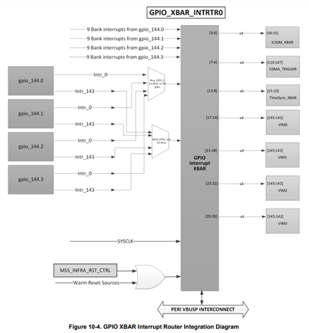
From the GPIO modules, 180 events/interrupts reach as input to GPIO Interrupt XBAR as shown in diagram below.
The 180 inputs contain both the individual GPIO interrupts (144 muxed from 4 GPIO modules) and also the 9 bank interrupts of 4 GPIO module
| Number of Interrupts | |
| Single GPIO Pin Interrupts | 144 |
| GPIO Bank Interrupts for instance 0 | 9 |
| GPIO Bank Interrupts for instance 1 | 9 |
| GPIO Bank Interrupts for instance 2 | 9 |
| GPIO Bank Interrupts for instance 3 | 9 |
| Total Inputs | 180 |
The below picture is taken from AM263 TRM - "Figure 10-4. GPIO XBAR Interrupt Router Integration Diagram"
GPIO Interrupt Route to R50_0:
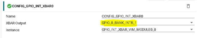
GPIO configuration for bank interrupt:
In the Current SDK 8.5 we have gpio_input_interrupt example using GPIO bank interrupt. The below reference is taken from GPIO app guide - https://software-dl.ti.com/mcu-plus-sdk/esd/AM263X/latest/exports/docs/api_guide_am263x/DRIVERS_GPIO_PAGE.html
In the example Go to SysCfg --> GPIO INT XBAR Option.
The following code can be taken as reference to configure the bank interrupt for HWIP:
static void GPIO_bankIsrFxn(void *args)
{
    uint32_t    pinNum = (uint32_t) args, bankNum;
    uint32_t    intrStatus, pinMask = GPIO_GET_BANK_BIT_MASK(pinNum);

    bankNum = GPIO_GET_BANK_INDEX(pinNum);
    intrStatus = GPIO_getBankIntrStatus(gGpioBaseAddr, bankNum);
    GPIO_clearBankIntrStatus(gGpioBaseAddr, bankNum, intrStatus);

    if(intrStatus & pinMask)
    {
        /*
        * Handle all the expected pin interrupts within a bank using intrStatus flag
        */
    }
}

void gpio_bank_interrupt_init(void)
{
    int32_t         retVal;
    uint32_t        pinNum = gGpioPinNum, bankNum;
    HwiP_Params     hwiPrms;

    bankNum = GPIO_GET_BANK_INDEX(pinNum);

    /* Interrupt setup */
    GPIO_setDirMode(gGpioBaseAddr, pinNum, GPIO_DIRECTION_INPUT);
    GPIO_setTrigType(gGpioBaseAddr, pinNum, GPIO_TRIG_TYPE_RISE_EDGE);
    GPIO_bankIntrEnable(gGpioBaseAddr, bankNum);

    /* Register bank interrupt */
    HwiP_Params_init(&hwiPrms);
    hwiPrms.intNum = gGpioBankIntrNum;
    hwiPrms.callback = &GPIO_bankIsrFxn;
    hwiPrms.args = (void *) pinNum;
    retVal = HwiP_construct(&gGpioHwiObject, &hwiPrms);
    if(SystemP_SUCCESS != retVal)
    {
        DebugP_assert(FALSE);
    }
}

void gpio_bank_interrupt_deinit(void)
{
    uint32_t        pinNum = gGpioPinNum, bankNum, intrStatus;

    bankNum = GPIO_GET_BANK_INDEX(pinNum);

    /* Interrupt disable and clear any pending interrupts */
    GPIO_bankIntrDisable(gGpioBaseAddr, bankNum);
    GPIO_setTrigType(gGpioBaseAddr, pinNum, GPIO_TRIG_TYPE_NONE);
    intrStatus = GPIO_getBankIntrStatus(gGpioBaseAddr, bankNum);
    GPIO_clearBankIntrStatus(gGpioBaseAddr, bankNum, intrStatus);

    /* Unregister interrupt */
    HwiP_destruct(&gGpioHwiObject);
}
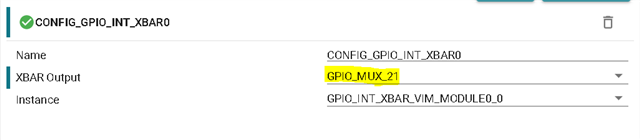
GPIO configuration for per pin interrupt:
To use the Individual GPIO Interrupt, change the XBAR Output option to respective GPIO_MUX pin required for you. Here ignore the "_MUX" in this context, this refers to the individual GPIO Pin only.
The following code can be taken as reference to configure the per pin interrupt for HWIP:
static void GPIO_pinIsrFxn(void *args)
{
    /*
     * Handle pin interrupt - This is pulse interrupt. No need to clear status
     */
}

void gpio_pin_interrupt_init(void)
{
    int32_t         retVal;
    uint32_t        pinNum = gGpioPinNum, bankNum;
    HwiP_Params     hwiPrms;

    bankNum = GPIO_GET_BANK_INDEX(pinNum);

    /* Interrupt setup */
    GPIO_setDirMode(gGpioBaseAddr, pinNum, GPIO_DIRECTION_INPUT);
    GPIO_setTrigType(gGpioBaseAddr, pinNum, GPIO_TRIG_TYPE_RISE_EDGE);
    GPIO_bankIntrEnable(gGpioBaseAddr, bankNum);

    /* Register pin interrupt */
    HwiP_Params_init(&hwiPrms);
    hwiPrms.intNum = gGpioPinIntrNum;
    hwiPrms.callback = &GPIO_pinIsrFxn;
    hwiPrms.args = (void *) pinNum;
    retVal = HwiP_construct(&gGpioHwiObject, &hwiPrms);
    if(SystemP_SUCCESS != retVal)
    {
        DebugP_assert(FALSE);
    }
}

void gpio_pin_interrupt_deinit(void)
{
    uint32_t        pinNum = gGpioPinNum, bankNum;

    bankNum = GPIO_GET_BANK_INDEX(pinNum);

    /* Interrupt disable and clear any pending interrupts */
    GPIO_bankIntrDisable(gGpioBaseAddr, bankNum);
    GPIO_setTrigType(gGpioBaseAddr, pinNum, GPIO_TRIG_TYPE_NONE);
    GPIO_clearIntrStatus(gGpioBaseAddr, pinNum);

    /* Unregister interrupt */
    HwiP_destruct(&gGpioHwiObject);
}
While acknowledging and checking the interrupt status for Individual and Bank GPIO Interrupts these APIs can be used:
| GPIO Bank | Individual GPIOs |
| GPIO_getBankIntrStatus | GPIO_getIntrStatus |
| GPIO_clearBankIntrStatus | GPIO_clearIntrStatus |
Thanks & Regards
Sri Vidya
