Other Parts Discussed in Thread: SYSCONFIG, UNIFLASH
Hi,
I want to store an application persistently. I can save my application in eMMC or OSPI when I use the AM64x Evaluation Module.
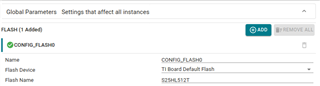
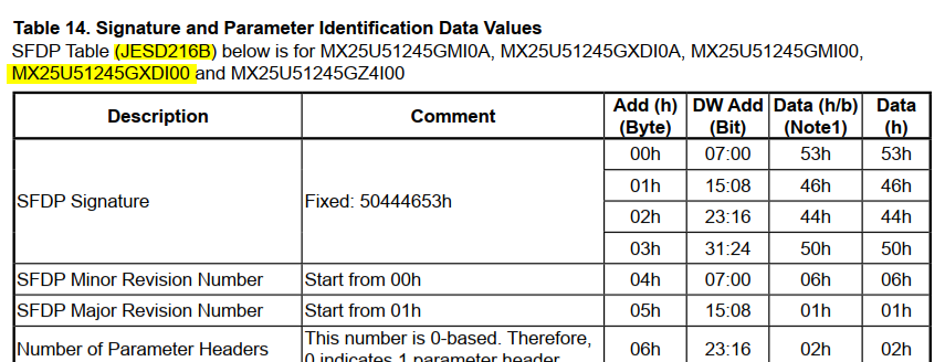
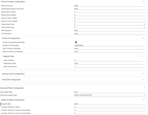
Now I want to save my application on costamer board. There we use a QSPI (MX25U51245GXDI00 from Macronix). When I follow the instruction for save application in QSPI or eMMC it doesn't work (https://software-dl.ti.com/mcu-plus-sdk/esd/AM64X/08_02_00_31/exports/docs/api_guide_am64x/TOOLS_FLASH.html).
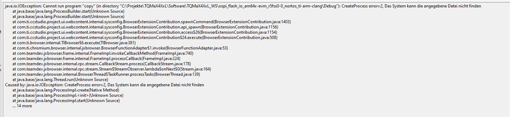
This error message is displayed:
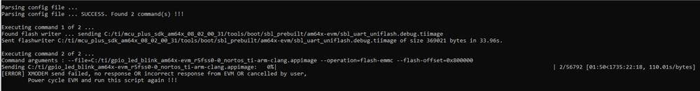
I think the problem is that the sbl uart unflash writes data to the OSPI flash whether the application is supposed to write to QSPI or eMMC. Writing to the OSPI flash doesn't work because we are using the QSPI flash.
I also tried to save the application to SD card but you can only save the application up to 380 kBytes and my application is bigger.
Can you help me to save my application persistently?
Best regards
Michael Bernhardt