This thread has been locked.

If you have a related question, please click the "Ask a related question" button in the top right corner. The newly created question will be automatically linked to this question.

TM4C1292NCPDT: Input current to be given to the isolator

Part Number: TM4C1292NCPDT

Hello,

We’re connecting TI launchpad to the adapter board having ADUM3151 isolator soldered on it (attached image_01) and giving 3.3V supply and SPI clock signal to the isolator.

While we're able to see the SPI clock signal on Side 1 of the isolator (as shown) but we're not getting any output signals on Side 2.

The current consumed on both the sides of the isolator is: IDD1: 2.8mA (1.5MHz) and IDD2: 5.4mA (1.5 MHz) 

On Side 2 of the isolator, we’re giving 8mA as supply current (see image_02) and the current consumed is 5.4mA (image_03) but when we reset the TI eval board, the LED of constant current(CC) starts glowing in the power supply and voltage drops from 3.3V to 2.6V (image_04) and we’re not getting any outputs on the signals of Side 2. 


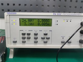
                     image_02                                                                                                           image_03                                                                                                            image_04

  • Hello Kiranjit,

    So the image_04 would indicate that the device is trying to source more energy than the current limit allows for which is pulling the voltage down as the current is sunk by the device.

    Beyond offering that thought, I am not sure what other guidance to offer here because it's not really clear to me how this issue specifically relates to our TM4C EVM.

    Best Regards,

    Ralph Jacobi

  • Hi Ralph,

    Thanks for your response!!

    After hardware reset from EV board , we found the issue as showing in Image_04.

    Please suggest your valuable thought to resolve this issue. 

    Attached reference schematic of design:

    Thanks,

    Kiranjit

  • Hello Kiranjit,

    I have no real expertise with isolators, so I can't really offer any guidance on my end. Understood that the MCU reset is the trigger point, but this sort of system issue isn't one I can offer debug guidance for a TM4C MCU expert.

    If you discover an MCU specific root cause that needs to be address, please share the details of that and I will do my best to explain how the MCU should be operating.

    Best Regards,

    Ralph Jacobi

  • but when we reset the TI eval board, the LED of constant current(CC) starts glowing in the power supply and voltage drops from 3.3V to 2.6V (image_04) and we’re not getting any outputs on the signals of Side 2. 

    Be aware the GPIO outputs enter high impedance state during POR. It is advisable to have external pull up/down resistors on any MCU pins that may have reverse current flow during that transition. If you find a GPIO pin has been stressed may require series resistor to keep it below datasheet maximum injection current.