Part Number: MSP432WARE
Hi all,
I am now creating a project with ADC14 but the AD result seems like a wrong value.
These are the code,
I have set P8SEL0 and P8SEL1 of ADC input channel.
unsigned long AD_Converter(unsigned short channel)
{
    unsigned long temp;
    unsigned short loop;

    temp=0;
    for(loop=0;loop<100;loop++)
    {
        __enable_irq();
        NVIC->ISER[0] |= 1 << ((ADC14_IRQn) & 31); //Enable ADC interrupt in NVIC module
        ADC14->CTL0 = ADC14_CTL0_SHT0_2 | ADC14_CTL0_SHP | ADC14_CTL0_ON; // Sampling time, S&H=16, ADC14 on
        ADC14->CTL1 = ADC14_CTL1_RES_3; // Use sampling timer, 14-bit conversion results
        switch(channel)
        {
            case Base:
                ADC14->MCTL[0] |= ADC14_MCTLN_INCH_21; // A21 ADC input select; Vref=AVCC
                break;
            case Back:
                ADC14->MCTL[0] |= ADC14_MCTLN_INCH_20; // A20 ADC input select; Vref=AVCC
                break;
            case Leg:
                ADC14->MCTL[0] |= ADC14_MCTLN_INCH_19; // A19 ADC input select; Vref=AVCC
                break;
        }
        ADC14->IER0 |= ADC14_IER0_IE0; // Enable ADC conv complete interrupt
        ADC_Flag=0;
        ADC14->CTL0 |= ADC14_CTL0_ENC | ADC14_CTL0_SC; // Start sampling/conversion
        while(ADC_Flag==0); // Use sampling timer, 14-bit conversion results
        temp+=ADC14->MEM[0];
    }
    temp=temp/100;
    return temp;
}

void ADC14_IRQHandler(void)
{
    ADC_Flag=1;
    ADC14->IER0 &= ~ADC14_IER0_IE0; // Disable ADC conv complete interrupt
}
The schematic wiring is a 15K-Ohm resistor and a VR connected to 3V3 power and GND.
Using ADC14 to transfer analog signal to digital signal.
I do not change VR but I got difference values of the ADC result.
Even I add a capacitance between ADC input channel and GND.
I have used a meter to measure the voltage of ADC channel and the voltage is the same value.
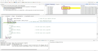
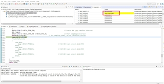
The following figures are the screenshot of the CCS debug environment.
I did not adjust the VR and the voltage value was not changed but I got the difference AD result.
How can I solve the problem?
Are there any mistake with my code?
BR,
Yu-Chuan, Chen