This thread has been locked.

If you have a related question, please click the "Ask a related question" button in the top right corner. The newly created question will be automatically linked to this question.

TMS570LS0432: VCC supply in the recommended range and VCCIO supply is not in the acceptable range

Part Number: TMS570LS0432

Hi,

We have our own design for the power supply reset of the controller (TMS570LS0432). We want to delay the reset of the controller when the VCCIO supply is not in the acceptable range. However, we have an additional chip that is capable of detecting the VCCIO under voltage and Over voltage conditions. And,  the SW will then control the nPORRST pin. 

We need the following information.

1.  The core runs on VCC supply (1.2V). (Same is true for RAM and FLASH memories. They all have VCC supply). Now, the question is, if the VCCIO supply is not in the acceptable range, Can the code execution be trusted?

2. Are there any consequences if we do not take care of the power-down sequence of the VCCIO supply with regard to the datasheet? Please see the section "6.2 Power Sequencing and Power-On Reset" of the data sheet.

Looking forward to hearing from you. Many thanks in advance,

Best regards,

Sreekanth Challa

  • Hi Sreekanth,

    We are working on your issue now and we will provide an update soon.

  • 1.  The core runs on VCC supply (1.2V). (Same is true for RAM and FLASH memories. They all have VCC supply). Now, the question is, if the VCCIO supply is not in the acceptable range, Can the code execution be trusted?

    No, both SRAM and Flash need 3.3V power supply. The MCU core and PLL use are powered by VCC (1.2V).

    2. Are there any consequences if we do not take care of the power-down sequence of the VCCIO supply with regard to the datasheet? Please see the section "6.2 Power Sequencing and Power-On Reset" of the data sheet.

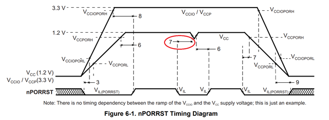
    There is no timing dependency between the ramp of the VCCIO and the VCC. The internal VMON will take care of them. 

    nPORRST: 1ms setup time is a MUST. It is nice to meet the 1ms hold time.  

  • Thanks for the response. 

    If the 3.3 volts is not in the acceptable range and memories (Flash and RAM) use 3.3 volts, does the controller results in ECC fault when accessing the memory and will this results in nERROR pin of the controller become active?

  • If VCCIO is not in the acceptable range, the peripherals may not work at all.  

  • I would like to provide more information here.  We have a system if the nERROR is pulled down to LOW -> The system is designed such that the CAN communication will be disabled. 

    This would be our primary diagnostics of the VCCIO supply.   So, if the VCCIO is not in the acceptable range where the RAM and Flash memories (RAM and Flash are based on 3.3 volts) can not be accessed correctly, Will that result in the nERROR pin become low?

    If that is the case, we are good to go. The diagnostics which we mentioned above is a single point fault. To achieve the latent point fault, we do intentionally control the nERROR pin on the startup to check whether that really disables the CAN communication or not.

    To point out what you mentioned (Peripherals do not work when the VCCIO is not in the acceptable range), the system uses SPI and CAN peripherals which are based on the 3.3 volts which would not work as well. We want to avoid the case where the system malfunctions such that CAN communication is perfectly active when there is a problem with 3.3volts. 

    We would like to know very specifically related to nERROR.

  • The ESM monitors device errors and determines whether the nERROR is pulled LOW when a fault is detected. The power failure (for example VCCIO below  the threshold 3.0V) can not be monitored by ESM. For example, the nERROR is asserted when an uncorrectable ECC error occurs in SRAM or Flash. 

    The VCCIO should be monitored by an external power supervisor. The reset must (nPORRST) be asserted by an external supervisor whenever the VCCIO or VCC are outside the specified recommended range (3V, and 1.14V). 

  • OK. Thanks for the response. I want to know specifically if the VCCIO is not monitored externally, (Since RAM and Flash memories are supplied by VCCIO),  If the VCCIO voltage is too low or too high (Below 2.7 volts and above 3.6 volts) -> Will that result in the ECC faults? 

  • I want to know specifically if the VCCIO is not monitored externally,

    Please check with your system design engineer if it is monitored externally. 

    If the VCCIO is <2.7V, the memory (SRAM and Flash) can not be accessed. If the VCCIO>3.6V, but <4.6V, the VCCIO will not corrupt the ECC value. Please be aware of that exposure to this condition (beyond recommended operating condition) for extended periods may affect device reliability.

  • Hi, I have been following this thread. 

    I would like to understand better the timing conditions for the reset line. You mentioned that the must condition is to have 1ms. setup time of nPORRST after VCCIO reaches the minimum high value.

    What about:

    • The 2 us requirement (tsu(porrst)). In the datasheet states, that the detection of VCCPORH needs to be done 2us before it reaches 1.14V. Is this really mandatory? What would happen if you reset after there is an UV in VCC?
    • Is there any similar requirement for VCCIO? Is it required to detect it and react faster than the UV (3.0V) reached the uC?
    • In case that those requirements are not required. What would be a good delay of detection? I can set an RC of a comparator to be even 200us and I would expect the decoupling caps of the UC would withstand fast current consumptions, leading to slow VCC UV conditions.
  • nPORRST: 1ms setup time is a MUST. It is nice to meet the 1ms hold time.  

    My statement is not correct. What I want to say is that "1ms hold time is a MUST, but it is nice to meet 2us setup time". 

  • My question is regarding the nº7. How critical is to detect that there will be an UV before reaching the minimum operating voltage. What is the impact if we reset later? In the end, it will reset the uC. 

    And the same question for VCCIO, is there such a requirement as number 7?

  • This setup time is to put the flash bank and flash pump to reset state before the power is lost completely. As I said, it is nice to meet this requirement. How do you predict voltage dip and insert this delay?