This thread has been locked.

If you have a related question, please click the "Ask a related question" button in the top right corner. The newly created question will be automatically linked to this question.

TMS570LC4357: Safety Feature HET5A "Boot Time Software Test of Function Using I/O Loopback" does not behave as expected.

Part Number: TMS570LC4357
Other Parts Discussed in Thread: TMDX570LC43HDK

Hi,

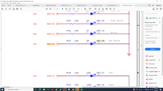
We are using the two High-End Timers (N2HET) for general-purpose I/O and we would like to perform the HET5A loopback test.
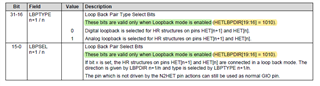
However, the test does not behave as expected because it appears that the Loop Back Pair Direction has to be the opposite to that specified in the Technical Reference Manual (SPNU563A) section 23.4.32 for it to work.

For instance.
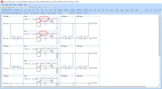
Step 1. Write 0x01 to HETLBPSEL to select digital loopback on pins 0 and 1.
Step 2. Write 0x01 to HETLBPDIR to set pin 0 as the output and pin 1 as the input.
Step 3. Enable loopback.
Step 4. Write to bit 1 of HETDIN.
Step 5. Check bit 0 of HETDOUT to confirm that it is the same value as written to pin 1 in step 4.

Is this procedure correct?

What I have found is that in step 5 pins 0 and 1 are not the same.

However, if in step 2 I write 0x00 to HETLBPDIR to set pin 1 as the output and pin 0 as the input, but continue to write to bit 1 in step 4, then in step 5 pins 0 and 1 are the same.

So, to get the test to pass I need to set HETLBPDIR to be the opposite to that specified in the Technical Reference Manual.

So, am I doing something wrong or is there an error in the Technical Reference Manual?


Thank you.

  • Hi Andrew,

    Started to work on your issue and we will provide an update very soon.

    --

    Thanks & regards,

    Jagadish.

  • Hi Andrew,

    Did you enable the loopback first before selecting loopback pair?

    --

    Thanks & regards,
    Jagadish.

  • Hi Jagadish,

    I have tried enabling the loopback before selecting the loopback pair but did not make any difference.

    Regards,

    Andrew

  • Okay, I will create an example code at my end.

  • Hi Andrew,

    I created an example and tested at my end it is working fine.

    Actually, after i studied i understood, by default HET[n+1] will act as output and HET[n] will act as input, so if i am not wrong may be you tried to write to the HET[n] which is input by default.

    HET_LOOPBACK_TEST_LC4357.zip

    /* USER CODE BEGIN (2) */
    #define ENANLE 0xA
    #define DISABLE 0x5
    #define LBPTSTENA_BIT_POS   16
    /* USER CODE END */
    
    int main(void)
    {
    /* USER CODE BEGIN (3) */
        hetInit();
        hetREG1->LBPDIR = ENANLE << LBPTSTENA_BIT_POS; //Enable Loopback
        hetREG1->LBPDIR &= ~(1 << 0); // HET1[1] as output and HET1[0] as input
        hetREG1->LBPSEL |= 1 << 0;  // Selecting Pair HET1[0] and HET1[1]
        hetREG1->LBPSEL &= ~(1 << 16); //Selecting Digital loopback
    
        hetREG1->DOUT |= 1 << 1;    //Writing 1 to HET1[1]
    
        if(hetREG1->DIN & 1 << 0) //Reading to HET1[0] and comparing with 1
        {
            hetREG1->DOUT &= ~(1 << 1); //Writing 0 to HET1[1]
            if((hetREG1->DIN & 1 << 0) == 0) //Reading to HET1[0] and comparing with 0
            {
                result = true;
            }
            else
            {
                result = false;
            }
        }
        else
        {
            result = false;
        }
    
        while(1);
    /* USER CODE END */
    
        return 0;
    }

    --

    Thanks & regards,
    Jagadish.

  • Hi Jagadish,

    Thank you for your reply.

    Your example code works for me.

    However, what I have observed is that this example causes the LEDs on the board to turn on.
    I am running this example on the TMDX570LC43HDK Hercules TMS570LC43x Development Kit.
    For instance if I change your example code so that HET1[29] is output and HET1[28] is input.
    Then write 0 to HET1[29] first followed by writing 1 to HET1[29].
    Then when while(true) is reached LED D8, Left bottom, is on.

    I was not expecting this behaviour because I thought that the loopback values would not be seen on the pins in Digital Loopback Mode.

    Do you see the same behaviour?

    Thank you.

    Andrew

  • Hi Andrew,

    Do you see the same behaviour?

    I don't see this behavior at my end because i tested this on Launchpad and not in HDK board

    Just now i verified the schematic of HDK board

    As you can see here HET1{29} connected to a LED on the HDK board, due to this LED is toggling whenever you are trying to write data on HET1[29].

    --

    Thanks & regards,
    Jagadish.

  • Hi Jagadish,

    Thank you for your reply.

    However, the issue is not related to the HDK.

    The issue is that the digital loopback test does not appear to be working as expected.

    For the digital loopback test my understanding is that the test signal should not be seen on the pins. I think that this means that the LEDs should not be illuminated.
    - Please confirm if my understanding is correct.

    But for me the LEDs are being illuminated which implies that the test signal is being seen on the pins.
    I have also tried the analog loopback test and it behaves in the same way as the digital loop back test i.e. for both the analog and digital loopback tests the LEDs are illuminated.
    There does not appear to be any difference between the analog and digital loopback tests.

    So, I do not think that the digital loopback test is working as it should.

    Do you have an explanation as to why, for the digital loopback test, the test signal seems to be seen on the pins and why the digital loopback test appears to work in the same way as the analog loopback test?

    Thank you.

    Andrew

  • Hi Andrew,

    For the digital loopback test my understanding is that the test signal should not be seen on the pins. I think that this means that the LEDs should not be illuminated.

    It is working as expected only, the actual meaning of digital loopback is there should not require any external wire to do loopback and loopback should happen internally. As you can see, we didn't use any external wire to short the HET1{28} and HET1{29} right?

    --

    Thanks & regards,
    Jagadish.

  • Hi Jagadish,

    Thank you for your reply.

    I agree with you that the digital loopback test does not require an external connection between the pins under test.

    However, my question is intended to clarify the difference between the analog and digital loopback tests.

    For the digital loopback you state that it "should not require any external wire to do loopback and loopback should happen internally".
    Are you implying that for analog loopback that an external wire is required and that loopback is done externally?
    If so then that was not my understanding. I thought that both analog and digital loopback were internal. Is this correct?

    Referring to the Technical Reference Manual (SPNU563A March 2018) section 23.2.5.7 Loop Back Mode describes the Digital Loopback and the Analog Loopback.

    For the Digital Loopback the TRM states "In digital loopback mode, the structure pairs are connected directly and the output buffers are bypassed. Therefore, the loopback values will NOT be seen on the corresponding pins."

    For the digital loopback what does "the loopback values will NOT be seen on the corresponding pins" actually mean?
    I thought that this means that the test signal does not reach the external pin and therefore the test signal cannot affect the external circuit or be affected by the external circuit.
    i.e. for example it would not turn on an external LED.

    For the Analog Loopback the TRM states "In analog loopback mode, the structure pairs are connected outside of the output buffers. Therefore, the loopback values WILL be seen on the corresponding pins.".

    For the analog loopback what does "the loopback values WILL be seen on the corresponding pins." actually mean?
    I thought that in this case it means that the test signal is present on the external pins and therefore is can affect the external signal.
    i.e. for example in this scenario it could turn on an external LED.


    Please clarify what the difference is between analog and digital loopback.

    Thank you,

    Andrew

  • Hi Andrew,

    My bad, i just used my old knowledge. But TRM was correct here.

    Yes, both digital loopback and analog loopback doesn't require any additional wires for loopback.

    Yes, digital loopback should not pass values to the output pins as output buffers are bypassed and in analog loopback the values will get pass to the output pins.

    I will test again at my end, why values are passing to the output pins in digital loopback.

    --

    Thanks & regards,
    Jagadish.

  • Hi Jagadish,

    Do you have an update on this issue?

    Thank you.

    Andrew

  • Hi Andrew,

    Apologies for the delay, i didn't get a chance to check this again due to other issues. I will start work on now and will provide an update soon.

    --

    Thanks & regards,
    Jagadish.

  • Hi Andrew,

    I checked it now and i could see the issue you mentioned at my end as well. But i could resolve the issue by commenting out the "hetInit" function.

    After commenting this function i could see proper operation for digital and analog loopbacks.

    In digital loopback i didn't see any values on the GIO pins(i.e. output buffers got disabled) but loopback worked as expected i.e. values written on HET1[0] got loopback to the HET1[1].

    In analog loopback i can see values on GIO pins (i.e. output buffers not disabled) and loopback also worked as expected i.e. values written on HET1[0] got loopback to the HET1[1].

    Can you please test the same and confirm from your end?

    --

    Thanks & regards,
    Jagadish.

  • Hi Jagadish,

    Thank you for your reply.

    I can confirm that if I comment-out the hetInit() function then I observe the same behaviour as you.
    i.e. In digital loopback the LEDs are not turned on.
    And in analog loopback the LEDs are turned on.

    In my case this is because I use hetInit() to configure the HET pins as GIO output.
    If hetInit() is not called then the default GIO direction is input.
    It appears to me that the configuration of the GIO direction overrides the analog/digital loopback configuration.

    I also use hetInit() to configure the module pull-ups/pull downs.
    So, not calling hetInit() is not really a satisfactory approach for me.

    I think that the problem is that the loopback behaviour for the HET module is not as described in the TRM. Do you agree?


    Thank you,
    Andrew

  • HI Andrew,

    In my case this is because I use hetInit() to configure the HET pins as GIO output.
    If hetInit() is not called then the default GIO direction is input.
    It appears to me that the configuration of the GIO direction overrides the analog/digital loopback configuration.

    You are right, if we configure pin direction as output then the output buffers not getting disabled even after we are configuring to digital loopback.

    So, not calling hetInit() is not really a satisfactory approach for me.

    Actually, no need to stop calling "hetInit" function you can call this function but just don't configure pin direction to output for the pins which we are using for loopback

    If you do that then you can call "hetInit" function and there won't be any problem. Once loopback testing completed, you can disable loopback and can configure required pin direction in the code itself.

    --

    Thanks & regards,
    Jagadish.

  • Hi Jagadish,


    Thank you for your reply.

    However, if I configure the pins as inputs instead of outputs, doesn't that just hide the problem?
    Isn't the fundamental problem that digital loopback does not appear to work? i.e. digital loopback appears to work in exactly the same way as analog loopback.
    If the pins are configured as inputs won't they receive signals from the external circuit and won't that affect the result of the loopback test?


    Regards,
    Andrew

  • Hi Andrew,

    However, if I configure the pins as inputs instead of outputs, doesn't that just hide the problem?

    Actually, the default state of the HET pins is input only.

    I mean we no need to configure the pin direction to the output if we want to perform HET loopback testings, you can directly enable the type of loopback, loopback pair and do the loopback testing.

    I won't say it is perfect, i will note down this behavior of digital loopback and will discuss with internal team.

    --

    Thanks & regards,
    Jagadish.