This thread has been locked.

If you have a related question, please click the "Ask a related question" button in the top right corner. The newly created question will be automatically linked to this question.

TM4C1292NCPDT: calculation of series resistor value

Part Number: TM4C1292NCPDT

Hi,

In reference to the following post;

(+) TM4C1292NCPDT: series resistor value - Arm-based microcontrollers forum - Arm-based microcontrollers - TI E2E support forums

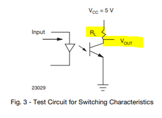
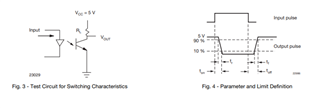
Please guide on how is the series resistor value decided for the connection.

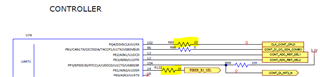
In my circuit, I'm connecting the output of optocoupler to a GPIO pin of microcontroller configured as input (signal 'DIN_SRC_SINKSEL1'). On the input side, I'm giving a signal of 24V and output is 3.3V.

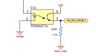
I want to calculate the series resistor value in the path from the output of optocoupler to the microcontroller (assuming 2mA current being supplied to the microcontroller).

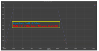
When I'm checking the current across the series resistor 10E or 1K, it's not showing any current drop.

Thanks,

Kiran

  • Hi,

      Are you sure you have the right connection? In the VOMA617A datasheet, it seems like you should be connecting Vout to the MCU GPIO input. I'm not familiar with VOMA617A and its correct operation. You should consult the vendor on how to connect to the MCU. 

  • Hi Charles,

    As you can see in below image, when we apply Input 24 V volt than output at collector terminal will be zero voltage.

    But we need 3.3 Volt so that we modified the circuit and took it from emitter terminal.

    Below is result of Altium simulation

    Now, we need series resistance value to interface output of optocoupler to microcontroller pin.

    Also, we made circuit on breadboard , put resistance and try to get the value of current using multi-meter but current was zero ampere.

    Please help us to find out the method to calculate the series resistance value for microcontroller.

    Thanks,

    Kiranjit

  • Hi,

    Also, we made circuit on breadboard , put resistance and try to get the value of current using multi-meter but current was zero ampere.

    If you are measuring 0 current with a 3.3V  input then you need to double check if you have damaged the MCU in the process of building your breadboard circuit.  What is the anticipated maximum output current from the optocoupler? I can't answer that question as I have no knowledge with the optocoupler .Normally NPN transistor is a current control device with very high collector current. the Rl should be placed on the collector. You need to make sure that high collector current does not damage the MCU.  

    As I suggest, please consult with your optocoupler vendor if your circuit is proper. 

  • Hi Charles,

    Thanks for your reply.

    OK, we will recheck breadboard circuit and optocoupler output current but 50mA is maximum output current as per datasheet. 

    Can you please share any document to calculate the series resistance for microcontroller interface?

    Thanks,

    Kiranjit 

  • I'm not aware of a document to calculate series resistance. Normally, to limit current to the MCU pin, I have seen people use as little as 22ohm or 10's to 100's is not unheard of.