This thread has been locked.

If you have a related question, please click the "Ask a related question" button in the top right corner. The newly created question will be automatically linked to this question.

AM2434: PLL Reference Clock Selection BOOTMODE[02:00] Pin floating, affect Boot Mode selection?

Part Number: AM2434
Other Parts Discussed in Thread: TMDS243EVM

Hi Experts,

Recently customer have encountered the problem that AM243x does not start work in their Board, exclude power supply issues, we find anything changed about BOOTMODE Pin when compared TMDS243EVM Schematic.

The customer's schematic diagram leaves BOOTMODE[02:00] floating, and only configures BOOTMODE[06:03] as below figure.

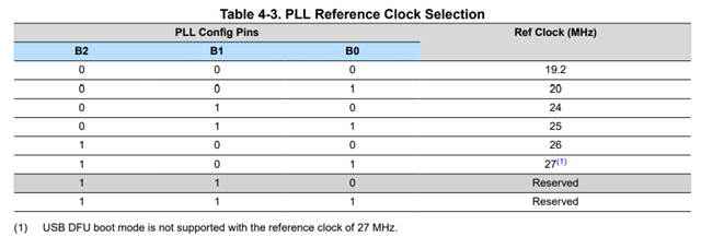
PLL Reference Clock Selection floating, affect Boot Mode selection? Will it also affect the start-up of the chip crystal oscillator? 

If so affect AM243x-Chip, are there other methods to solve it? 

The customer is in a hurry to test, and if it needs to be changed, it needs to re-modify the board and make a PCB. Please help to me check it. Thanks.

  • Hi,

    If the BOOTMODE[2:0] pins are left floating (and not connected to anything else on the schematic that could be applying a voltage), the device has very weak internal pulldowns on these lines that should make these pins read as a 0 when they are read during boot.  So this would expect a reference clock of 19.2 MHz.  If this is a mismatch with what is implemented on the design, then you could see issues botting the AM243x device.

    It looks like there are DNI'd pull resistors on the BOOTMODE[2:0] pins in the schematic snippet shown.  Are they able to try populating the correct pull resistors to select the correct Ref Clock frequency?

    Thanks,
    Mike

  • Hi Mike,

    Customer uses the 25MHz active crystal oscillator on their board, and we test the 3V3 and PORz_Out normal(Always 3.3V high level) during power up.

    But our JTAG emulator unable to connect to the target core and also Setup UART Terminal (UART0), POWER-ON the their board, we can not see the character "C" getting printed on the UART terminal every 2-3 seconds, So we doubt that the RBL code in AM243x not work, or any other H/W error to cause this phenomenon. Any suggestion from your side?

  • Hello Mike,

    When connect the Target with XDS100 Emulator, POWER-ON the their board, connect the Core, it reports the below Error -1170 @ 0x0.

    When connect the UART0, POWER-ON the their board, it no response. The same operation, our EVM board can work normally.  Any suggestion?

  • This discussion is being continued offline and will be updated once a resolution is found.

  • The customer updated the board design to include the pull resistors on all of the BootMode pins, including BootMode7, and is now able to connect to their HSFS device over JTAG as expected.