This thread has been locked.

If you have a related question, please click the "Ask a related question" button in the top right corner. The newly created question will be automatically linked to this question.

MSP432E401Y: two question about SPI and STE

Part Number: MSP432E401Y

Hi Team,

There are two question from the customer:

1.under what situation the clock start working

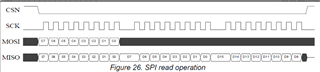
My impression is that when the data is filled in the sending buffer, it will start. I am learning SI24R1 recently, using SPI communication. The timing is shown on the right. After sending the read command (C7--C0),  How can I get the effect of the black area on the upper right to receive the read data?

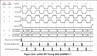
2.About the control of STE signal in 4-wire master mode

Here, take STE as a low level to make the slave active as an example. In the picture on the left (MSP432 official technical manual), the STE is pulled up after sending 1 byte each time. Is this done automatically by the hardware after the IO port is configured? If so, is the 4-wire mode not working properly to control SI24R1 (as shown in the figure on the right, the host receives multiple bytes continuously, and the CSN must be kept, that is, STE is low)

Could you help check this case?

Thanks & Regards,

Ben

  • Hello Ben,

    How can I get the effect of the black area on the upper right to receive the read data?

    That would just indicate a "don't care" period so it doesn't matter what is present on the data line at that time.

    Here, take STE as a low level to make the slave active as an example. In the picture on the left (MSP432 official technical manual), the STE is pulled up after sending 1 byte each time. Is this done automatically by the hardware after the IO port is configured? If so, is the 4-wire mode not working properly to control SI24R1 (as shown in the figure on the right, the host receives multiple bytes continuously, and the CSN must be kept, that is, STE is low)

    That is correct understanding of how the eUSCI module operates. To avoid this issue, most customers just manually control the STE line by not configuring it as a eUSCI signal and instead configuring it as a GPIO which can be raised high & low as needed for reads and writes.

    Best Regards,

    Ralph Jacobi