This thread has been locked.

If you have a related question, please click the "Ask a related question" button in the top right corner. The newly created question will be automatically linked to this question.

LP-AM243: Undocumented I2C boot selection IO expander

Part Number: LP-AM243

I want to drive LP-AM243 board from the other device: specifically, reset it into UART bootloader mode, update the firmware, then reset back to boot from flash.

To do that, I need to know how to set boot mode via the I2C IO expander. However I haven't found any relevant information in the User Manual at https://www.ti.com/tool/LP-AM243#tech-docs 

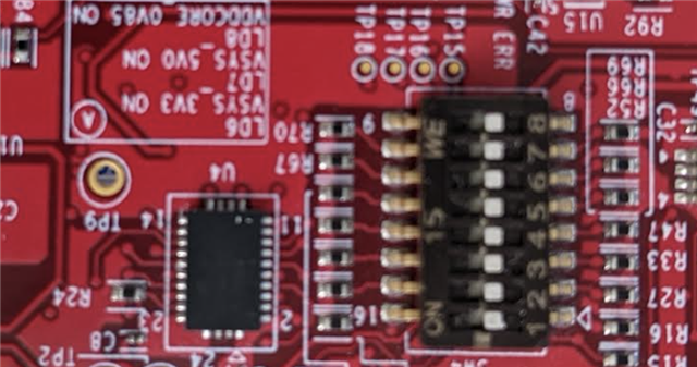
Section 4.16 (rev.C) mentions the expander, it mentions I2C pins - but says nothing about the expander part number, address, etc.

Question. Is there any other way to update LP-AM243 firmware in an automated way? Otherwise, how I2C can be used to do that?

  • Hi ,

    I can link you to the expert who can help you out with the hardware but there is a smarter way to handle the same via SW.

    In case you are not interested to use the flash, you can use the I2C EEPROM to store the information for FW Update.

    Hope this helps.

    Best Regards,
    Aakash

  • Aakash,

    Thank you. Unfortunately your response does not answer the question.

    I am able to find an expander part number from the schematics file: TCA6408ARGTR

    I could see the relevant bit in a schematic:

    I'd be grateful if someone from TI can confirm .

  • Hi ,

    As mentioned in the LP-AM243 User Manual, Section 4.16 Test Automation Interface, yes the Test Automation Header J15 on board can be used to

    1. Reset AM243.
    2. Control Bootmode using the IO Expander U26(TCA6408ARGTR). Please ensure all the Bootmode switches on SW4 are on the same state so it is easier to program U26 output pins. The U26 gets powered on through U41 on board during Power On(or can be powered externally through Test Automation header for programming the IO Expander before LP-AM243 power ON). Please ensure the states of the IO Expander are held until the SOP pins are sampled by AM243. The I2C address can be found in the TCA6408ARGTR datasheet, Figure 8-9. The U26's Address pin(16) is set to 0(zero) using R177 on board. So, the I2C address will be 0b0100000, in 7 bit addressing and adding the last read/write bit makes corresponding 8-bit I2C address.

    Before implementation, please cross verify the external Test Automation header connections you will be connecting, with the Test Automation circuitry on board LP-AM243(Refer Pages 20 and 21 of 29 in RevC Schematics).

    I hope this answers what you were looking for.

    But I would say the approach suggested by  above to be an easier approach for firmware update, which would need lesser hardware infrastructure, compared the approach of using the Test Automation header.

    Thanks,
    Tejas Kulakarni

  • Thank you.

    In my case, I need the board be updated by an external device. Thus the software solution is not applicable.

    Side note - it is very inconvenient to have test headers broken out the way they are (FPC connector), especially only several pins are functional there. I had to go elsewhere and buy an adapter. Why doing this on a development board, what should make exactly these things easy? A rhetoric question, but please consider in the future designs.

    Appreciate your help.

  • Hi Sergey Lyubka,

    Thank you for the feedback, we will consider changing the Test Automation header to a connector that is easier to use.

    Thanks,
    Tejas Kulakarni

  • Thank you.

    According to the schematic, the board was designed by Mistral, not TI. Please let them know.

    Also, please let them now that the manual: https://www.ti.com/lit/ug/spruj12c/spruj12c.pdf?ts=1677579446051  Has sections 4.2-4.17 duplicated. Apparently someone accidentally copy-pasted things and that copy-paste found its way to the manual. I think that should be corrected, too.

  • Hi Sergey Lyubka,

    Thanks a lot for noticing that. I have internally pointed out to update the User guide.

    Is there anything else that you need help with? Please let us know.

    Thanks,
    Tejas Kulakarni

  • Yes please.

    I'd like to have some assistance with the test automation interface. Specifically, how to drive the IO expander. I don't seem to get any response from it. My actions:

    1. I have set all DIP switches that control boot mode, to "off":

    2. I wired an external micro to the test header, pins 37 (CLK) and 39 (SDA):

    3. I scanned the I2C bus, addresses from 0 to 120, and got no response.

    4. I verified other pins of the test automation header - e.g. 1,2,3,7 - and they are indeed 3v3 & GND, per spec.

    5. I connected to the BoosterPack headers and scan I2C0 pins, I get expected responses from addresses 80, 81, 96.

    What I am missing? How can I talk to the bootmode IO expander?

  • Hi Sergey Lyubka,

    Few quick checks,

    1. The external header(FPC breakout FPC-40P 0.5mm) pin numbers in the image you have above, shows that the pin numbers start from Bottom right(in the above image) with Pin 1, so the pins 37 and 39 should be on the bottom left of the black connector. I see two wires(these are the SDA SCL wires from your I2C controller?) connected to pins 2 and 4, so please cross-verify if those are correct.
    2. Also, you would have to connect the GND from your I2C Controller along with the SDA and SCL, please ensure this too.
    3. On the LP-AM243 board, the IO Expander gets power through "VCC3V3_TA" net, so please check once on TP49 to see if the LDO U41 which powers the IO Expander is powered On or not.

    Thanks,
    Tejas Kulakarni

  • Tejas,

    Thank you for following up. I think my pinout was correct.

    I've marked the pins on my picture:

    1. I checked TP49 : it has 3v3 indeed.

    2. I checked pins 1,2,3 - they have 3v3.

    3. Pin 7 is 0 volt, and it is connected to the GND  (my tester beeps)

    4. Pin 40 also GND (beeps)

    5. Pins 37, 39 are 3v3 , which I think is correct, since SDA and SCL should be high when idle.

    My external MCU is wired to the 3v3 and GND of the booster pack. I believe GND is shared, because if I touch the GND on my external MCU and pin 40 on the test header, it beeps.

    I cannot talk to the expander. If I re-wire my MCU to use I2C0 on the booster pack, I can talk to the I2C devices indeed - address 80,81,96. I use 100kHz I2C frequency.

    Do you have any clue what I may have done wrong?

  • Hi Sergey Lyubka,
    Everything looks fine, not sure what we are missing.

    If you have access to an Oscilloscope, can you please probe once on the LP-AM243's J15 Test Automation header I2C pins(Pins 37 and 39), and check if you can see the I2C transactions when the I2C controller tries to communicate to the IO Expander(U26)? This is just to ensure we are indeed getting the I2C signals onto the IO Expander from the external I2C controller.

    Thanks,
    Tejas Kulakarni

  • Tejas,

    Thank you for your support.

    It turned out, the problem was a loose FPC cable connection. When corrected, the expander indeed answers on address 32.