This thread has been locked.

If you have a related question, please click the "Ask a related question" button in the top right corner. The newly created question will be automatically linked to this question.

MSP432-DEBUGGERS: MSP432P401R Cannot get I2C Repeated Start condition to work properly

Part Number: MSP432-DEBUGGERS


I am trying to implement an I2C Read function to support the KT0806L_V1.8  FM Modulator device which requires a  repeated start condition in my MSP432 project:

I am running the Bluetopia Stack v4.2.1.1.  The write works fine, however when trying to do a read that has a repeated start condition I run into problems because the peripheral wants to send a stop condition after the write command is sent with the address value of where the read is suppose to happen from. This causes the sequence to end and the read return invalid data.

I have read many threads and I have seen how you must trick the peripheral inside of the TX Isr by switching modes to Receive before the last byte goes out, etc.  This is how the sample driver library(below) tries to do it but that does not work for me with the default sample project: 

C:\temp\msp432_driverlib_3_21_00_05\msp432_driverlib_3_21_00_05\examples\MSP432P4xx\i2c\i2c_master_rw_repeated_start-master_code.

I was able to get the following code supplied by a user on this forum to work in a stand alone sample project:

https://e2e.ti.com/support/microcontrollers/msp-low-power-microcontrollers-group/msp430/f/msp-low-power-microcontroller-forum/650134/msp432p401r-in-i2c-master-how-to-send-one-byte-to-slave-repeat-start-and-read-one-byte-by-interrupt-method

However, when I port this to my A3DPDemo_Src  project it does not work.  The stop condition is generated by the peripheral and kills the repeat start condition thus breaking the read function all together and causing the state machine on the KT Micro device to return incorrect data for the read. 

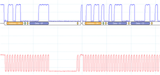
This is a good read using the sample code I got from the link above.  You can see the stop condition happens and the read brings back a valid value.

And when adding the same code in my Project  you can see that the stop condition happens and read returns bad data:

Furthermore, the sequence never ends leaving the peripheral in an unknown state.

Since I noticed that the I2C peripheral is very timing dependent I would like to add that the sample code is running at 3MHz MCLK speed and baud rate of 100Kbps while my Project has a 24Mhz clock and 100Kbps baud rate.  I essentially tried to increase the delays in the code by 8X but that did not work.

This is the code I am using for both the sample project and the project I am developing on.

    //Turn on FM Mod
    GPIO_setOutputHighOnPin(GPIO_PORT_P4, GPIO_PIN6);
    //GPIO_setOutputHighOnPin(HRDWCFG_FM_EN_PORT_NUM, HRDWCFG_FM_EN_PIN_NUM);
    GPIO_setAsOutputPin(GPIO_PORT_P4, GPIO_PIN6);

    /* Disabling the Watchdog */
    MAP_WDT_A_holdTimer();

    /* Select Port 1 for I2C - Set Pin 6, 7 to input Primary Module Function,
     *   (UCB0SIMO/UCB0SDA, UCB0SOMI/UCB0SCL).
     */
    MAP_GPIO_setAsPeripheralModuleFunctionInputPin(GPIO_PORT_P1,
            GPIO_PIN6 + GPIO_PIN7, GPIO_PRIMARY_MODULE_FUNCTION);

    /* Initializing I2C Master to SMCLK at 400kbs with no autostop */
    MAP_I2C_initMaster(EUSCI_B0_BASE, &i2cConfig);

    /* Specify slave address */
    MAP_I2C_setSlaveAddress(EUSCI_B0_BASE, SLAVE_ADDRESS);

    /* Set Master in transmit mode */
    //MAP_I2C_setMode(EUSCI_B0_BASE, EUSCI_B_I2C_TRANSMIT_MODE);

    /* Enable I2C Module to start operations */
    MAP_I2C_enableModule(EUSCI_B0_BASE);

    __delay_cycles(10000);

        /* Send out start + address + 1 data byte */
    MAP_I2C_masterSendMultiByteStart(EUSCI_B0_BASE, TXData);

    //wait for first byte to be moved to shift register
    while(!(EUSCI_B0->IFG & EUSCI_B_IFG_TXIFG));
    EUSCI_B0->IFG &= ~(EUSCI_B_IFG_TXIFG);

    // Before the restart is sent, app has to wait for current TX byte + ack to complete
    // This takes 9 cycles at 100kHz = 90uS
    // The MCLK default = ~3MHz
    // to complete the 1 byte TX app needs to wait ~270 MCLK cycles at a minimum
    __delay_cycles(300);

    //clear the TR bit to setup master as receiver
     EUSCI_B0->CTLW0 &= ~(EUSCI_B_CTLW0_TR);
    // Send the start + address
     EUSCI_B0->CTLW0 |= EUSCI_B_CTLW0_TXSTT;
    // wait for address to be sent
    while(!(EUSCI_B0->CTLW0 & EUSCI_B_CTLW0_TXSTT));
    // set stop immediately to ensure only one byte is read
    EUSCI_B0->CTLW0 |= EUSCI_B_CTLW0_TXSTP;
    // poll RX flag
    while(!(EUSCI_B0->IFG & EUSCI_B_IFG_RXIFG0));
    // Read from Receive buffer
    RXData = EUSCI_B0->RXBUF;
    // ensure I2C transaction has completed
    while (MAP_I2C_masterIsStopSent(EUSCI_B0_BASE));

Thanks in advance for helping me out with this issue.

  • Hello Ozzy,

    Sorry for the delay in initial reply, you've provided a lot of detail and done a lot of leg work here. Our engineering team is reviewing these details internally and will aim to provide initial feedback next week.

    Best Regards,

    Ralph Jacobi

  • Hello Ozzy,

    From what we can determine based on your specific issue versus what has been previously resolved, it looks like the issue you are facing is largely timing based for your specific use case as you were able to get the original solution working on its own. Increasing the delay was going to be one of the suggestions and maybe that needs to be further investigated to see if there is a delay interval that does work.

    As far as additional ideas go, one path that could be explored is to reference the following MSP430 example which has register-level calls: https://dev.ti.com/tirex/explore/node?devices=MSP430F5529&devtools=MSP430F5529&node=A__AAgA6nQUp0MrAIFqRqRUrA__msp430ware__IOGqZri__LATEST

    The eUSCI interface between the MSP432P4 and that MSP430 device operate the same, so that example with repeated start functionality would be the best reference point to offer beyond what is provided already with the MSP432 SDK.

    Best Regards,

    Ralph Jacobi

  • Ralph,

    I have played around with the delay by making it proportionate with the the MCLK speed of my project and that did not work.  I have also tried other other values and have had no luck. 

    Why is it so difficult to perform the repeated Start condition?   The example in your driver library does not work btw or at least I could not get it to work.

    Is the MCLK speed too fast to perform this task?

    Ozzy

  • Hello Ozzy,

    The example I referenced above is for another TI MCU which has the eUSCI interface that is in the MSP432P4 device and that example relies fully on DRM level coding - by avoiding the use of DriverLib APIs, it may be possible the timing issue can be resolved. At least that's the thought behind offering the alternative code as a possible solution.

    I wouldn't think MCLK is too fast because those other MCUs weren't significantly slower in comparison.

    Best Regards,

    Ralph Jacobi

  • The code that I am currently using is also DRM for the most part except for set up and the initial send ..   I can break down initial send portion to DRM level and see if  that helps and get back to you.

  • Hello Ozzy,

    I was able to get ahold of another engineer to review your situation with and a couple ideas that came from that review are:

    1. Since the example project is running at 3 MHz and that works, can you add clock configuration code to that example in order to get the MCLK running at 24 MHz? This would allow you to test the combination of the higher system clock plus 8x increase on delay in the working example code. If that works correctly then the issue would be more specific to your application but if the example code breaks at the higher clock rate than the root cause is that the workaround provided has a limit.
    2. If running at 24 MHz with the extended delay does not work, then a question that comes up is if the sequence of checking flags etc. is executing too rapidly. For example perhaps the initial delay is important, but if the code executes too quicky then the repeated start is coming out quicker than it would at 3 MHz and is being registered as a stop condition instead - part of that thought is due to how the waveform for the repeated start signal seems to be a narrower spike for your 24MHz code.

    If the issue is repeatable for a MSP432 LaunchPad at 24 MHz with the basic example code, then that would allow us to replicate the failure and look into the flags etc. as well.

    Best Regards,

    Ralph Jacobi

  • Ralph,

    I went back and made all of the code DRM and this didnt work.

    I then checked the MCLK speed of the sample project that works vs the MCLK of my application.  The sample project is running at 3Mhz while the A3DPDemoSource project is running at 24Mhz which is needed to handle the Bluetopia stack and the MIPS required to maintain BT working. I started to increase the sample project MCLK speed to see if it could handle the faster clock.  At 6 Mhz the Repeat Start condition works fine and at 12 Mhz as well after increase the delay that happens after the module is enabled.  However once I go to 24Mhz it breaks and I start to see the same results that I see in my project. 

    Has anyone tested the I2C repeat start condition at 24Mhz MCLK?   Other functionality works but not the repeat start condition.

    Regards,

    Ozzy

  • Hello Ozzy,

    Has anyone tested the I2C repeat start condition at 24Mhz MCLK?   Other functionality works but not the repeat start condition.

    I'm guessing not given the prior E2E posts etc.

    Can you share the revised example code project you test where 24 MHz is not working and showing the same results as your Bluetopia project? That will let us start from the same point you are at so we can review the timings / delays etc. to see what might be breaking the process with the higher MCLK speed.

    Best Regards,

    Ralph Jacobi

  • Hello Ozzy,

    While testing the previously provided example, my colleague was able to re-create the code breaking at 24 MHz on a MSP432P4 LaunchPad talking another LaunchPad. Based on this an adjustment was made to add before checking for the flag which is followed by the stop bit. For their testing that resolved the issue.

    The code for that is as follows:

    /* --COPYRIGHT--,BSD
     * Copyright (c) 2017, Texas Instruments Incorporated
     * All rights reserved.
     *
     * Redistribution and use in source and binary forms, with or without
     * modification, are permitted provided that the following conditions
     * are met:
     *
     * *  Redistributions of source code must retain the above copyright
     *    notice, this list of conditions and the following disclaimer.
     *
     * *  Redistributions in binary form must reproduce the above copyright
     *    notice, this list of conditions and the following disclaimer in the
     *    documentation and/or other materials provided with the distribution.
     *
     * *  Neither the name of Texas Instruments Incorporated nor the names of
     *    its contributors may be used to endorse or promote products derived
     *    from this software without specific prior written permission.
     *
     * THIS SOFTWARE IS PROVIDED BY THE COPYRIGHT HOLDERS AND CONTRIBUTORS "AS IS"
     * AND ANY EXPRESS OR IMPLIED WARRANTIES, INCLUDING, BUT NOT LIMITED TO,
     * THE IMPLIED WARRANTIES OF MERCHANTABILITY AND FITNESS FOR A PARTICULAR
     * PURPOSE ARE DISCLAIMED. IN NO EVENT SHALL THE COPYRIGHT OWNER OR
     * CONTRIBUTORS BE LIABLE FOR ANY DIRECT, INDIRECT, INCIDENTAL, SPECIAL,
     * EXEMPLARY, OR CONSEQUENTIAL DAMAGES (INCLUDING, BUT NOT LIMITED TO,
     * PROCUREMENT OF SUBSTITUTE GOODS OR SERVICES; LOSS OF USE, DATA, OR PROFITS;
     * OR BUSINESS INTERRUPTION) HOWEVER CAUSED AND ON ANY THEORY OF LIABILITY,
     * WHETHER IN CONTRACT, STRICT LIABILITY, OR TORT (INCLUDING NEGLIGENCE OR
     * OTHERWISE) ARISING IN ANY WAY OUT OF THE USE OF THIS SOFTWARE,
     * EVEN IF ADVISED OF THE POSSIBILITY OF SUCH DAMAGE.
     * --/COPYRIGHT--*/
    /******************************************************************************
     *  MSP432 I2C - EUSCI_B0 I2C Master TX 1 bytes to MSP432 Slave
     *  and reads one byte back following a repeated start
     *
     *  Description: This demo connects two MSP432 's via the I2C bus. The master
     *  transmits to the slave. This is the MASTER CODE.
     *  _________________________________________________________
     *  |  Start   |      |  Start   |                   |       |
     *  | 0x48Addr | 0x04 | 0x48Addr |  <1 Byte Read>    |  Stop |
     *  |    W     |      |    R     |                   |       |
     *  |__________|______|__________|___________________|_______|
     *
     *  ACLK = n/a, MCLK = HSMCLK = SMCLK = BRCLK = default DCO = ~3.0MHz
     *
     *                                /|\  /|\
     *                MSP432P4111     10k  10k      MSP432P4111
     *                   slave         |    |         master
     *             -----------------   |    |   -----------------
     *            |     P1.6/UCB0SDA|<-|----+->|P1.6/UCB0SDA     |
     *            |                 |  |       |                 |
     *            |                 |  |       |                 |
     *            |     P1.7/UCB0SCL|<-+------>|P1.7/UCB0SCL     |
     *            |                 |          |                 |
     *
      *****************************************************************************/
    /* DriverLib Defines */
    #include <ti/devices/msp432p4xx/driverlib/driverlib.h>
    
    /* Slave Address for I2C Slave */
    #define SLAVE_ADDRESS       0x48
    #define NUM_OF_REC_BYTES    1
    
    /* Variables */
    const uint8_t TXData[] = {0x41,0x42};
    unsigned char RXData=0;
    
    /* I2C Master Configuration Parameter */
    const eUSCI_I2C_MasterConfig i2cConfig =
    {
            EUSCI_B_I2C_CLOCKSOURCE_SMCLK,          // SMCLK Clock Source
            24000000,                                // SMCLK = 3MHz
            EUSCI_B_I2C_SET_DATA_RATE_100KBPS,      // Desired I2C Clock of 100khz
            0,                                      // No byte counter threshold
            EUSCI_B_I2C_NO_AUTO_STOP                // No Autostop
    };
    
    int main(void)
    {
        /* Disabling the Watchdog  */
        MAP_WDT_A_holdTimer();
    
        /* Select Port 1 for I2C - Set Pin 6, 7 to input Primary Module Function,
         *   (UCB0SIMO/UCB0SDA, UCB0SOMI/UCB0SCL).
         */
    
        MAP_CS_initClockSignal(CS_MCLK, CS_MODOSC_SELECT, CS_CLOCK_DIVIDER_1);
        MAP_CS_initClockSignal(CS_SMCLK, CS_MODOSC_SELECT, CS_CLOCK_DIVIDER_1);
    
        MAP_GPIO_setAsPeripheralModuleFunctionInputPin(GPIO_PORT_P1,
                GPIO_PIN6 + GPIO_PIN7, GPIO_PRIMARY_MODULE_FUNCTION);
        MAP_GPIO_setAsOutputPin(GPIO_PORT_P3, GPIO_PIN0);
    
        /* Initializing I2C Master to SMCLK at 100khz with no autostop */
        MAP_I2C_initMaster(EUSCI_B0_BASE, &i2cConfig);
    
        /* Specify slave address */
        MAP_I2C_setSlaveAddress(EUSCI_B0_BASE, SLAVE_ADDRESS);
    
        /* Enable I2C Module to start operations */
        MAP_I2C_enableModule(EUSCI_B0_BASE);
    
        /* Send out start + address + 1 data byte */
        MAP_I2C_masterSendMultiByteStart(EUSCI_B0_BASE, TXData[1]);
    
        //wait for first byte to be moved to shift register
        while(!(EUSCI_B0->IFG & EUSCI_B_IFG_TXIFG));
        EUSCI_B0->IFG &= ~(EUSCI_B_IFG_TXIFG);
    
        // Before the restart is sent, app has to wait for current TX byte + ack to complete
        // This takes 9 cycles at 100kHz = 90uS
        // The MCLK default = ~3MHz
        // to complete the 1 byte TX app needs to wait ~270 MCLK cycles at a minimum
        __delay_cycles(2500);
    
        //clear the TR bit to setup master as receiver
         EUSCI_B0->CTLW0 &= ~(EUSCI_B_CTLW0_TR);
    
        // Send the start + address
         EUSCI_B0->CTLW0 |= EUSCI_B_CTLW0_TXSTT;
    
         __delay_cycles(250);
    
        // wait for address to be sent
        while(!(EUSCI_B0->CTLW0 & EUSCI_B_CTLW0_TXSTT));
        // set stop immediately to ensure only one byte is read
        EUSCI_B0->CTLW0 |= EUSCI_B_CTLW0_TXSTP;
        // poll RX flag
        while(!(EUSCI_B0->IFG & EUSCI_B_IFG_RXIFG0));
        // Read from Receive buffer
        RXData = EUSCI_B0->RXBUF;
        // ensure I2C transaction has completed
        while (MAP_I2C_masterIsStopSent(EUSCI_B0_BASE));
    
        while(1);
    }
    

    The delay inserted is 250 cycles, and from the testing, 100 cycles was not sufficient, but 200 and above works fine. 250 was chosen to leave some buffer.

    Please see if that adjustment works for both your example project and your Bluetopia project. If it does not work with your example project, we'll need to get your example project posted to compare setup etc.

    Best Regards,

    Ralph Jacobi

  • Ralph,

    This did the trick. 

    Thank you,

    Ozzy