This thread has been locked.

If you have a related question, please click the "Ask a related question" button in the top right corner. The newly created question will be automatically linked to this question.

AM2432: Add breakpoint failed: Register/Memory read failure[22004]

Part Number: AM2432
Other Parts Discussed in Thread: AM2434

I am trying to set a breakpoint on R5FSS1-0 core on a AM2432

I have CCS 12.2.0.00009, SDK mcu_plus_sdk_am243x_08_05_00_24, syscfg 15.0, compiler CLANG 2.1.2

If I don't set any breakpoint the firmware run normally

If I start debugging from main step by step, no issues.

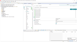
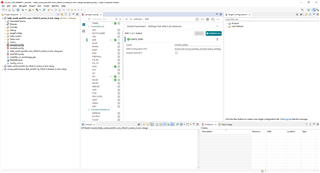
But as soon as I set a breakpoint I get this message:

Here is my map file: canopen.Debug.map

Here is the binary .out: canopen_am243x-titan-prod_r5fss1-0_nortos_ti-arm-clang.out

Looking forward

  Andrea

  • Hi 

    This breakpoint failed message comes when that particular code or when you are accessing a memory that is not compiled or not part of the .out

    Could you check if you are able to access that part of code, is it compiled?

    Are you getting this error in all places of the code or only in a particular area?

    Thanks & Regards

    Sri Vidya

  • Hi  Sri Vidya Gunturi,

       yes actually it seams the breakpoint tries to point to a memory location not reachable by the ARM core and not part of .out
    I tried to point to several parts of the code and the behavior is the same.

    Looking forward

       Andrea

  • Hi Andrea

    Are you pausing the core when you are trying to put breakpoint?

    you cannot put breakpoint when the core is running.

    If you are able to start debugging from main step by step, then break point in those places should work fine.

    Regards

    Sri Vidya

  • Of course I am pausing the core.

       Andrea

  • Hi Andrea

    Please allow me some time to cross check with the .out you have provided.

    Thanks for your patience.

    Regards

    Sri Vidya

  • Hi Andrea

    Is DDR being used in your setup?

    Regards

    Sri Vidya

  • Yes, sure, we have DDR and it works.

    The firmware is loaded properly even into DDR but in my linker file I have:

    MEMORY
    {
        R5F_VECS  : ORIGIN = 0x00000000 , LENGTH = 0x00000040
        R5F_TCMA  : ORIGIN = 0x00000040 , LENGTH = 0x00007FC0
        R5F_TCMB0 : ORIGIN = 0x41010000 , LENGTH = 0x00008000
    
        /* memory segment used to hold CPU specific non-cached data, MAKE to add a MPU entry to mark this as non-cached */
        NON_CACHE_MEM : ORIGIN = 0x70068000 , LENGTH = 0x8000
    
        /* when using multi-core application's i.e more than one R5F/M4F active, make sure
         * this memory does not overlap with other R5F's
         */
        MSRAM_CORE_0_IEC61850     : ORIGIN = 0x70080000 , LENGTH = 0x40000
        MSRAM_CORE_1_CAN          : ORIGIN = 0x700C0000 , LENGTH = 0x40000
    
        /* This section can be used to put XIP section of the application in flash, make sure this does not overlap with
         * other CPUs. Also make sure to add a MPU entry for this section and mark it as cached and code executable
         */
        FLASH     : ORIGIN = 0x60180000 , LENGTH = 0x80000
    
        /* shared memory segments */
        /* On R5F,
         * - make sure there is a MPU entry which maps below regions as non-cache
         */
        USER_SHM_MEM            : ORIGIN = 0x701D0000, LENGTH = 0x00002000
        USER_INIT_SHM_MEM       : ORIGIN = 0x701D2000, LENGTH = 0x00002000
        LOG_SHM_MEM             : ORIGIN = 0x701D4000, LENGTH = 0x00004000
        RTOS_NORTOS_IPC_SHM_MEM : ORIGIN = 0x701D8000, LENGTH = 0x00008000
        /* DDR must be partitioned and assigned to core 0 and core 1 */
        DDR_CORE_0_IEC61850     : ORIGIN = 0x80000000, LENGTH = 0x04000000 /* 64 MB */
        DDR_CORE_1_CAN          : ORIGIN = 0x84000000, LENGTH = 0x04000000 /* 64 MB */
        DDR_SHARED              : ORIGIN = 0x88000000, LENGTH = 0x04000000
    }
    

  • Hi Andrea

    Sure, we will look into this.

    Regards

    Sri Vidya

  • Hi Andrea,

    It is probably due to incorrect MPU settings for DDR4, Please add the following in the example.syscfg for R5F1_0 --> MPU ARMv7:

    Best regards,

    Ming

  • Hi Ming,

       I am sorry but it isn't an issue related to MPU.

    I don't start neither Core R5FSS0-0 nor Core R5FSS1-0.

    I connect JTAG to Core R5FSS0-0, load firmware, then connect to R5FSS1-0 and load its firmware.

    Then, BEFORE to run, I try to add a breakpoint in the firmware of core R5FSS1-0 and I get the error message.

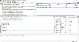
    As you can see from the screenshot, both cores are stopped and core R5FSS1-0 execution flow is ready to start from main (my red arrow).

    I try to add a breakpoint in the place rounded in red and I get the error message.

    (messages from the console attached after the screenshot)

    Looking forward.

        Andrea

    MAIN_Cortex_R5_0_0: Error: (Error -1170 @ 0x0) Unable to access the DAP. Reset the device, and retry the operation. If error persists, confirm configuration, power-cycle the board, and/or try more reliable JTAG settings (e.g. lower TCLK). (Emulation package 9.10.0.00080)
    MAIN_Cortex_R5_0_0: Unable to determine target status after 20 attempts
    MAIN_Cortex_R5_0_0: Failed to remove the debug state from the target before disconnecting. There may still be breakpoint op-codes embedded in program memory. It is recommended that you reset the emulator before you connect and reload your program before you continue debugging
    MAIN_Cortex_R5_1_0: Error: (Error -1170 @ 0x0) Unable to access the DAP. Reset the device, and retry the operation. If error persists, confirm configuration, power-cycle the board, and/or try more reliable JTAG settings (e.g. lower TCLK). (Emulation package 9.10.0.00080)
    MAIN_Cortex_R5_1_0: Unable to determine target status after 20 attempts
    MAIN_Cortex_R5_1_0: Failed to remove the debug state from the target before disconnecting. There may still be breakpoint op-codes embedded in program memory. It is recommended that you reset the emulator before you connect and reload your program before you continue debugging

  • Hi Andrea,

    I still since it is the MPU settings. From your screen shot all breakpoints you tried to set are in DDR4. There is an easy way to tell whether it is DDR4 related or not. Allocate you code to the on-chip memory (0x70000000, 2MB) instead of in the DDR4. If you still have this problem, then it is not related to DDR. If the problem goes away, then it is DDR4 related. 

    Please also share your linker.cmd and example.syscfg for both R5F_0_0 and R5F_1_0.

    Best regards,

    Ming

  • Hi Ming Wei,

       I tried to use SW breakpoints and it works.

    So, why with HW breakpoints it doesn't ?

    canopen.sycfg

    linker.cmd

    iec61850.syscfg

       Andrea

  • Hi Andrea,

    Are you using the SBL_NULL in flash/SD card or use GEL to initialize the board before loading your OUT file?

    Can you try to add a DDR in canopen.syscfg?

    Best regards,

    Ming

  • Yes, I use SBL_NULL in flash to initialize the board and DDR (this is why it isn't included in canopen.syscfg).

    I tried also to add a hardware breakpoint in on-chip memory and the effect is the same (so it isn't related to DDR)

    Looking forward

       Andrea

  • Hi Andrea,

    I noticed the location where you tried to set the HW breakpoint at (0x700C0151) is in MSRAM_CORE_1_CAN (0x700C0000) of the linker.cmd. Since MSRAM_CORE_1_CAN is used for all the .text sections in that linker.cmd, I assume this linker.cmd is for R5F_1_0 project. Is it possible the linker.cmd for R5F_0_0 also put the .text into the same area (0x700C0000)?

    Can you also share the linker.cmd file for the R5F_0_0 and the map file for both projects?

    Best regards,

    Ming

  • Hi Ming Wei,

        here is linker.cmd for R5F_0_0: linker.cmd

    Here are map files:

    iec61850.Debug.map

    canopen.Debug.map

    Looking forward

       Andrea

  • Hi Andrea,

    From your canopen.Debug.map. It looks like you are trying to set a HW breakpoint at the Trampoline location. That may not be possible. Can you try to set the breakpoint at where the function code is located (0x84003b6c)?

    HwiP_Params_init $Tramp$TT$L$PI$$HwiP_Params_init
    700c0151 84002de4 84003b6c drivers.am243x.r5f.ti-arm-clang.debug.lib : ipc_notify_v0.obj (.text.IpcNotify_init)

    Best regards,

    Ming

  • Hi Andrea,

    As I recall, you can set the breakpoint to this location, but not HW breakpoint correct?

    Can you set the HW breakpoints ate other locations, like in main()?

    Best regards

    Ming

  • Hi Ming Wei,

      correct, I can set SW breakpoint but not HW breakpoints.

    After I load the image on core R5FSS1-0 I see the code execution stopped at main, but if I try to add any other HW breakpoint in parts of the code it fails.

    Looking forward

      Andrea

  • Hi Andrea,

    Got it! I will look into it and get back to you soon.

    Best regards,

    Ming

  • Hi Ming Wei,

       any update ?

    Thanks

       Andrea

  • Hi Andrea,

    I cannot reproduce your failure case on my EVM. I tried to put the code and data for R5F_0_0 (empty example) into the DDR (0x80000000) and the code and data for R5F_1_0 (empty example) into DDR (0x84000000). I connected and loaded program to both cores. I still can set the hardware breakpoints without any issue. See the attached screen shot:

    I looked into your canopen.Debug.map and noticed that the DDR_CORE_1_CAN is only used for very small portion (~95KB). Can you move everything from DDR_CORE_1_CAN  to  MSRAM_CORE_1_CAN and see whether the hardware breakpoint can be set or not?

    This way, we can rule out the DDR or MPU setting related issues completely.

    Best regards,

    Ming

  • Hi Ming Wei,

       the situation is releated to the SoC revision !!

    I have tried to reproduce the problem on my board with AM2434 GP and it works without any issue.

    Then, I returned to the production board AM2432 HS-FS and I tried to LOAD (not to run ... ) the ipc example ipc_rpmsg_echo.

    I tried with an example to avoid dependencies related to my firmware.

    I builded the r5fss1-0_nortos part for core 1-0, then loaded on R5FSS1-0 and added a hardware breakpoint before to run: IT FAILED !

    I builded the r5fss0-0_freertos part for core 0-0, then loaded on R5FSS0-0 and added a hardware breakpoint before to run: it worked.

    So, please, make your tests with a board having a SoC AM2432 HS-FS because we have a real issue with a mass production SoC and this has a serious impact on our business.

    Sincerely

       Andrea

  • Hi Andrea,

    I did the same tests on a AM243x EVM with HS-FS chip on. I was able to set the HW breakpoint on both R5F_0_0 and R5F_1_0. See the attached screenshot.

    One thing I did is to flash the sbl_prebuilt/am243x-evm/sbl_null.release.hs_fs.tiimage (from the MCU+ SDK for AM243x 08.05.00.24) into the OSPI flash of the AM243x EVM. It will do the SOC and board initialization for the EVM, so that the CCS can connect to the targets (R5F_0_0 and RF_1_0).

    Best regards,

    Ming

  • Hi Ming Wei,

        sure I have also flashed the sbl_null bootloader, this is why CCS can connect to both cores.

    Please, could you share with me your debug configuration ?

    I suspect it could be something related to it.

    Looking forward

       Andrea

  • Hi Andrea,

    I did use no gel file for any of the R5F cores and DMSC, since the sbl_null has done the SOC initialization. That may be the cause.

    Attached please find the ccxml file I used for testing.

    https://e2e.ti.com/cfs-file/__key/communityserver-discussions-components-files/908/AM243x_5F00_EVM_5F00_no_5F00_launch.ccxml

    Best regards,

    Ming

  • Hi Ming Wei,

       good, this debug configuration works well, without any issue related to HW breakpoint.

    By the way, now you should discover why our debug configuration doesn't work (it is just the generic one for AM2432_AVL).

    Here is the link, please test it:

    https://drive.google.com/file/d/1yyB891Ej83MF1ag3aYHs-snavrw9oybw/view?usp=share_link

    Looking forward

       Andrea

  • Hi Andrea,

    I cannot access to your google drive file, can you attach your ccxml file in this e2e thread?

    The only difference of my ccxml file with the generic one is that mine does use gel file for any R5F cores nor the DMSC core.

    Best regards,

    Ming

  • Hi Ming Wei,

      sorry but e2e let me attach only images, not generic files, this is why I used a link.

    Anyway, the main difference is that in my configuration I have only 2 cores, not 4.

    If there is a bug in CCS could be that the "second" core must be R5FSS0-1 but in AM2432 the "second" core is R5FSS1-0.

    Please try a debug configuration with AM2342_AVL. (not AM2434).

    Thanks

      Andrea

  • Hi Andrea,

    I tried the newly created ccxml file (without gel files) for the AM2432_ALV on AM243x EVM. I can set up the HW breakpoint for R5F_0_0 and R5F_1_0.

    Attached please find the ccxml file for AM2432_ALV.

    There is no bug in the CCS regarding to the R5F cores. There two clusters in the AM243x SoC. Each cluster has two R5F cores. When you use AM2434_ALV, then all 4 R5F cores are used R5F_0_0 and R5F_0_1 belong to the 1st cluster and the R5F_1_0 and R5F_1_1 belong to the 2nd cluster. If you are using the AM2432_ALV, then only the first R5F core of each cluster are used, i.e. only the R5F_0_0 and R5F_1_0 are used. This way, the whole 128KB TCM in the same cluster can be used by the R5F core in the cluster.

    Best regards,

    Ming

    https://e2e.ti.com/cfs-file/__key/communityserver-discussions-components-files/908/AM2432_5F00_evm_5F00_no_5F00_gel.ccxml