Hi, Expert
I would like to reduce the load by assigning the functions and variables used in the PWM ISR to TCMA and TCMB.
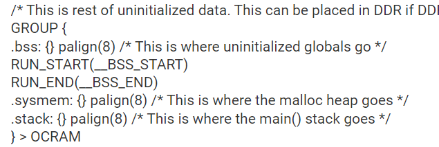
All functions and variables were assigned to the TCM area by referring to the link below. (checked through .map file)
However, as a result of measuring the load, the performance rather deteriorated.
The test proceeded as follows.
1. Source Code
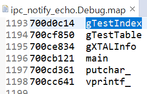
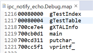
uint32_t gTestIndex __attribute__((__section__(".controldata")));
uint32_t gTestTable[1000] __attribute__((__section__(".controldata")));
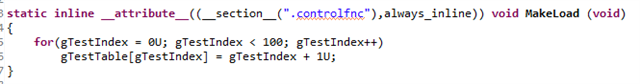
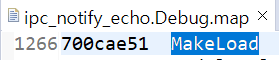
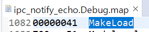
__attribute__((__section__(".controlfnc"))) void MakeLoad (void)
{
for(gTestIndex = 0U; gTestIndex < 1000; gTestIndex++)
gTestTable[gTestIndex] = gTestIndex + 1U;
}
uint16_t gCounterBufferStart[100];
uint16_t gCounterBufferEnd[100];
uint16_t gCounterBufferDiff[100];
uint32_t gCounterBufferStartIndex = 0U;
uint32_t gCounterBufferEndIndex = 0U;
static void EPWM_ISR(void *handle)
{
volatile bool status;
if(gCounterBufferStartIndex < 100)
{
gCounterBufferStart[gCounterBufferStartIndex++] = EPWM_getTimeBaseCounterValue(0x50080000ul);
}
else
{
/*NOP */
}
MakeLoad();
if(gCounterBufferEndIndex < 100)
{
gCounterBufferEnd[gCounterBufferEndIndex] = EPWM_getTimeBaseCounterValue(0x50080000ul);
gCounterBufferDiff[gCounterBufferEndIndex] = gCounterBufferEnd[gCounterBufferEndIndex] - gCounterBufferStart[gCounterBufferEndIndex];
gCounterBufferEndIndex++;
}
else
{
/*NOP */
}
status = EPWM_getEventTriggerInterruptStatus(gEpwmBaseAddr);
if(status == true)
{
EPWM_clearEventTriggerInterruptFlag(gEpwmBaseAddr);
}
return;
}
2. Test configuration
- PWM ISR occurs at TBC 0
- In order to measure the time during which MakeLoad is executed, TBC is measured before and after the function, and the load is evaluated as the difference value.
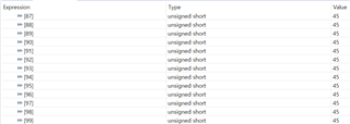
3. Test Result
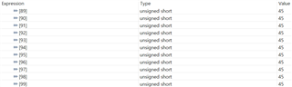
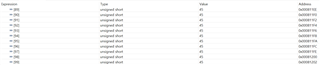
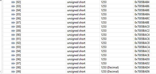
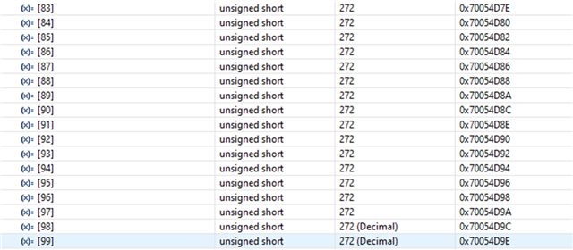
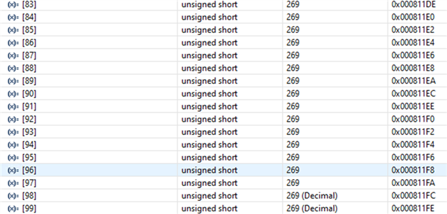
- If functions and variables are not assigned to the TCM via the "__attribute__" reserved word:
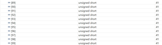
Result of both function and variable being allocated in OCRAM
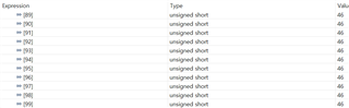
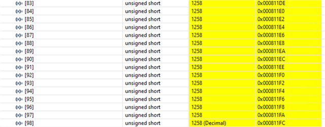
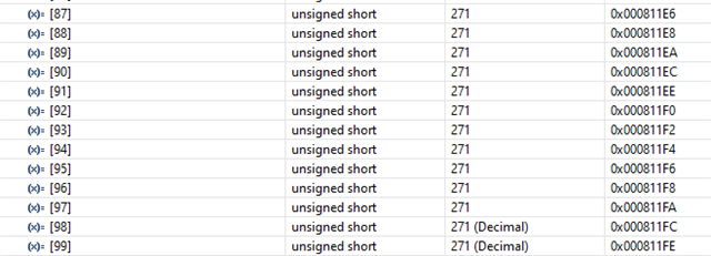
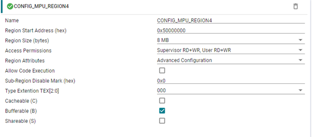
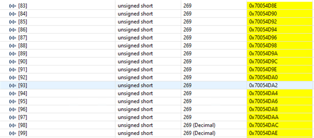
- If functions and variables are assigned to the TCM via the "__attribute__" reserved word:
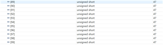
Result assigned to TCMA for function and TCMB for variable
The above code was written for testing, and the code to be applied in practice is more complex.
However, the load increased when the actual code was assigned to TCM in the same way.
What are these causes?
Please let us know if you have any data needed for analysis.
Best Regards
Jiung Choi