


Part Number: EK-TM4C129EXL
Other Parts Discussed in Thread: CCSTUDIO
Hi,
I am working on a platform that will be using the TM4C129ENCPDT Arm chip. For development, I'm using the EK-TM4C129EXL and referencing the following TivaWare API.
Description:
The goal of the design is to have some other host board act as an i2c/smbus master, which would trigger the slave interrupt. The master will send multi-byte write commands and single byte read commands. When prompted for a read, the slave will also need to respond with multiple bytes. Due to the multi-byte transactions, I want to leverage the i2c FIFO peripheral functionality. I have some basic functionality "working" (code posted below), but there are several quirks that I am running into, so I have several questions about the provided TivaWare API and my implementation of it.
To test my slave drivers, I am using the protocol feature on an Analog Discovery 2 (AD2) to act as an i2c master.
Theory of Operation:
- master sends read or write request
- this causes the i2c slave interrupt to trigger
- in the interrupt, the slave calls I2CSlaveStatus(...) to determine the type of message received from the master
- if the master is writing data, store the data in the provided buffer to move it out of the FIFO
- if the master is requesting a read, it will have first sent a write message telling the slave to put the data in the Tx buffer, which will then get read out on the subsequent read command
Code:
Note - the status variable isn't doing anything, I am having issues with the I2CSlaveStatus(...) call. See question 1 below.
uint8_t buffer[4] = {0};
uint8_t constBuffer[4] = {0xA0, 0xB0, 0xC0, 0xD0};

void i2cIntHandler(void)
{
    uint32_t status = I2CSlaveStatus(I2C0_BASE);

    if(status == I2C_SLAVE_ACT_RREQ)
    {
        status = status;
    }
    else if(status == I2C_SLAVE_ACT_TREQ)
    {
        status = status;
    }
    else
    {
        status = status;
    }

    uint8_t x = 1;
    uint8_t index = 0;
    while(x)
    {
        status = I2CSlaveStatus(I2C0_BASE);
        x = I2CFIFODataGetNonBlocking(I2C0_BASE, &buffer[index]);
        index++;
    }

//    while(x)
//    {
//        status = I2CSlaveStatus(I2C0_BASE);
//        x = I2CFIFODataGetNonBlocking(I2C0_BASE, buffer);
//    }

    for(uint8_t i = 0; i < 4; i++)
    {
        I2CFIFODataPutNonBlocking(I2C0_BASE, constBuffer[i] + buffer[i]);
    }

    I2CSlaveIntClear(I2C0_BASE);
}

void initSMBus(void)
{
    GPIOPinConfigure(GPIO_PB2_I2C0SCL);
    GPIOPinConfigure(GPIO_PB3_I2C0SDA);
    GPIOPinTypeI2CSCL(GPIO_PORTB_BASE, GPIO_PIN_2); // configure SCL line
    GPIOPinTypeI2C(GPIO_PORTB_BASE, GPIO_PIN_3);    // configure SDA line

    SysCtlPeripheralEnable(SYSCTL_PERIPH_I2C0);
    while(!SysCtlPeripheralReady(SYSCTL_PERIPH_I2C0));

    uint8_t address = 0x12;
    I2CSlaveInit(I2C0_BASE, address);
    I2CSlaveFIFOEnable(I2C0_BASE, I2C_SLAVE_RX_FIFO_ENABLE | I2C_SLAVE_TX_FIFO_ENABLE);
    I2CRxFIFOConfigSet(I2C0_BASE, I2C_FIFO_CFG_RX_SLAVE | I2C_FIFO_CFG_RX_TRIG_4);
    I2CTxFIFOConfigSet(I2C0_BASE, I2C_FIFO_CFG_TX_SLAVE | I2C_FIFO_CFG_TX_TRIG_4);

    I2CSlaveIntEnable(I2C0_BASE);
    I2CIntRegister(I2C0_BASE, i2cIntHandler);
}
Read and Write Results:
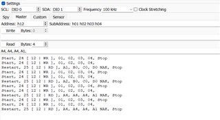
The transactions are kinda working. I am using the subaddress field as a hacky way to send data when doing a read command - which the AD2 sends as a write then a read. I'd expect the output to always be A1 B2 C3 D4 after every read command. Using the debugger, I confirmed that the write messages are not getting fully parsed in, but I'd still expect to see the A B C D elements of the read since those are just hard coded constants. Furthermore, the read output changes. I think I have a fundamental misunderstanding as to how these FIFOs are supposed to be implemented. Insight is appreciated.
Questions:
- I am using the I2CSlaveStatus call to determine what kind of message the master sent us. Using that differentiation will allow me to actually separate out that Tx and Rx FIFO accessing so they don't occur in every interrupt, like they do in my code example. However, I have noticed that this call is always returning zero. At one point, I was detecting the I2C_SLAVE_ACT_TREQ status by using breakpoints in the CCStudio debugger; however, I am unable to reliably implement that API call. This is a pretty important call in the slave design, so I'd really like to get it working.
- In the initialization code on lines 57 and 58, what are those CFG TRIG_# flags? The API says it's the trigger level. What does that mean? Is it the FIFO size at which some triggering interrupt flag will occur?
- What are the FIFO sizes? I can't find any details about their specifics in the provided documentation.
- I cannot find any examples on how to use this slave elements of this API anywhere online. Any examples or feedback on how these FIFOs actually work would be greatly appreciated.
Thank you for your help,
Zach

