This thread has been locked.

If you have a related question, please click the "Ask a related question" button in the top right corner. The newly created question will be automatically linked to this question.

MCU-PLUS-SDK-AM263X: Pin questions for AM263 E2

Part Number: MCU-PLUS-SDK-AM263X

Looking at the PROC110E2 schematic I have a few questions:

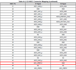
1) Pin 43 is listed as NC in the Hardware User's Guide (page 49: https://www.ti.com/lit/ug/spruj09c/spruj09c.pdf?ts=1676648505407) but in the PROC110E2 schematic I see a resistor connecting this pin to GND. 

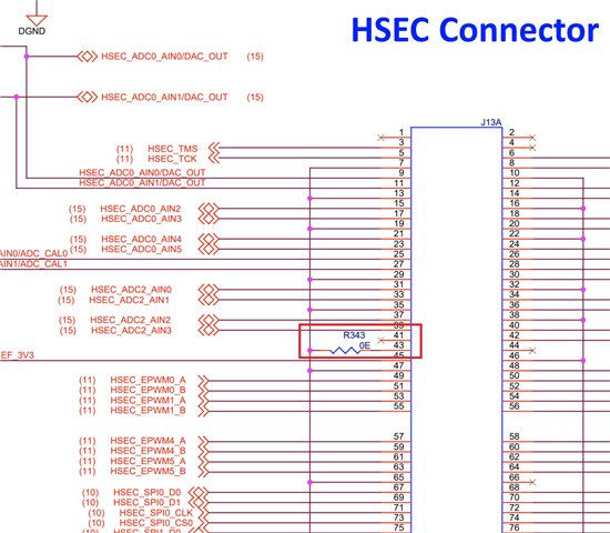
is this resistor R343 normally a do-not-install? I don't see an alternate function for this pin so am curious why R343 was included at all.

2) In the same Hardware User's Guide linked above I see a possible error. Pins 133 and 134 have the exact same alternate functions list, was this a typo? What are the alternate functions of pins 133 and 134 actually?

3)

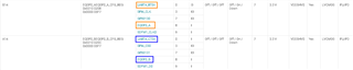
The same Hardware User's Guide linked above has conflicting assignments for UART4_RTSn and UART4_CTSn.

In Pinmux Mapping (page 41, Table 4-22) I see

*UART4_RTSn on pin B14 along with primary function EQEP0_A

*UART4_CTSn on pin A14 along with primary function EQEP0_B

In E2 Pinout (page 50, Table 4-24) I see 

*UART4_CTSn on pin 102 with EQEP0_A

*UART4_RTSn on pin 100 with EQEP0_B

which table is correct?

Regards,

-Adrian

  • Hey Adrian,

    Thank you for your patience while our experts were OOO on business travel.

    1) HSEC Pin 43 is connected to ADC_VREFLO directly in the E1 design of the Control Card. For the E2 design, this was determined to be redundant as ADC_VREFLO is connected directly to GND via a OΩ resistor. Pin 43 can either be NC by removing R343 or GND by keeping it installed. 

    2) This is a typo in the muxed signals column for Pin133. Pin 134 is correct as listed. This will be resolved in the next release.

    Pin133 Muxed Signal Options are: RGMII2_TD2, MII2_TXD2, EPWM29_A, GPMC0_A9, GPIO101

    3) This is a typo in the E2 Pinout (Table 4-24) and will be resolved in the next release.

    • UART4_RTSn is on pin B14 (EQEP0_A)
    • UART4_CTSn is on pin A14 (EQEP0_B)

    Best Regards,

    Zackary Fleenor