This thread has been locked.

If you have a related question, please click the "Ask a related question" button in the top right corner. The newly created question will be automatically linked to this question.

RM46L852: Micro SDXC High Endurance for the RM46L852

Part Number: RM46L852
Other Parts Discussed in Thread: TMDXRM46HDK

Hello, my name is Francisco, engineer of the R+D+i Department of the Rother Industries & Technology company. I would want to use a MicroSDXC of 64 or 128 GB, but it would communicate with the RM46L852 microcontroller via SPI protocol. Therefore, I have contacted Sandisk about a microSDXC that meets this requirement, they told me that the most suitable card for this application is the Micro SDXC High Endurance, but they recommended me that I should contact Texas Instrument about this issue. So I would like to know your opinion about it and what Micro SDXC I could use for an application where the host (RM46L852) will be writing data on the cards continuously (every 10 ms).

According to Physical Layer Simplified Specification of SD Association, the feature of SPI communication is mandatory for SDXC cards. An example of this aplication is the TMDXRM46HDK Development kit.

Please, explain the reasons for your answers. I would appreciate the answer from an expert who has studied the Physical Layer Specification.

Best regards,

Francisco.

  • Hello Jagadish.

    Thanks for your comment, but this is not what I'm asking.

    I already have the example code (which is outdated and not efficient) and before writing this post I had already read the Physical Layer Specification and asked Sandisk to verify me the SPI mode support for the SDXC card, so it is correct. My question is knowing which SDXC card is best suited to the application that I have mentioned, since as Sandisk has recommended I should ask Texas Instrument for this information.

    Best regards,

    Francisco.
  • Hi Francisco,

    which SDXC card is best suited to the application that I have mentioned

    We never interfaced any SDXC card with RM46 or any other hercules controller, so it is difficult for us to judge which SDXC card will be suitable for your application.

    (RM46L852) will be writing data on the cards continuously (every 10 ms).

    And as you want to write for every 10ms

    And write performance of micro SDXC is 60MB/S, so you can easily write 600KB in 10ms. I guess it would be sufficient for your application, i don't think you will get a requirement to write more than 600KB of data in 10ms.

    --

    Thanks & regards,
    Jagadish.

  • Hi Jagadish,

    I had already supposed this situation because the example code is not prepared to use SDXC card. However, I think that technical support of Texas Instrument should know this aspect, in other words, the micro SD is used in the development kit called TMDXRM46HDK so I consider it fundamental that the technical support know about all sd card that support SPI mode (SDUC card does not support this mode) and they provide us the minimum features or sd card examples that we could use for this microcontroller. The reason for this is based on what Sandisk support told me, they commented me that Texas Instrument is the responsible to know the support requirements.

    On the other hand, with respect to the write performance, I interpreted in the Physical layer SD Card that the maximum speed for the write and read operations is limited to 25 MB/s for the SPI mode. So, Can you provide me the source (documents) where is explained the way SDXC could reach to 60 MB/s? It would be very interesting for my application and others.

    Can you provide me the source of the picture that you have sent me?

    Best regards,

    Francisco.

  • Hi Francisco,

    On the other hand, with respect to the write performance, I interpreted in the Physical layer SD Card that the maximum speed for the write and read operations is limited to 25 MB/s for the SPI mode.

    You are right about this, the maximum speed we can go by using SPI is 25MHz.

    As min SPICLK period is 40ns so that max frequency is 25MHz only.

    So, Can you provide me the source (documents) where is explained the way SDXC could reach to 60 MB/s?

    SanDisk Extreme® microSDXCTm UHS-I CARD, 4K UHD, Full HD | Western Digital

    --

    Thanks & regards,
    Jagadish.

  • Hi Jagadish,

    Thanks for your reply, I have studied the document that you have sent me. However, this document is about the normal SDXC card, but I would like to get information about the High Endurance SDXC card.

    However, my questions are not resolved, please Jagadish or other person, that knows about High Endurance SDXC card or SDXC card and has studied the Physical Layer Specification for SD card, try to reply the following questions:

    1) Which are the features that the SDXC card, concretely High Endurance SDXC card, must meet to work with the RM46L852 microcontroller via SPI?

    2) As Jagadish and me have been able to verified, the maximum frequency of the SPI protocol is 25 MHz, in other words, the SD card work in default speed mode. I attach the picture where appears the speed feature of the SD Card in this mode (Picture getting of the Physical Layer Specification). I transmit 40 bytes maximum each 10 ms from RM46L852 microcontroller  to SD card to 25 MHz and bus speed to 12.5 MB/s, so I would have transmitted 125 KB of data in 10 ms. Would it be correct?

    3) Would it be possible to read and write on the High Endurance SDXC via SPI each 10 ms or is there any limitation for this microcontroller?

    Best regards,

    Francisco.

  • Hi Francisco,

    I will discuss with my internal team on this before providing answers for above questions.

    --

    Thanks & regards,
    Jagadish.

  • Hi Jagadish,

    Thanks and best regards,


    Francisco.

  • Somebody could help me? I am still waiting for an answer, 13 days have passed and Texas Instrument has not yet provided relevant information on this subject. This shows how little knowledge Texas Instrument has about using SD cards in their microcontrollers, but they still decide to sell development kits that include SD card communication capability.

  • Hi Francisco,

    I discussed the issue with my colleague QJ, who have huge experience in Hercules related controllers.

    The conclusion is we don’t have experience of using SDXC card. If the card supports SPI mode, SPI baud rate should not be a matter.

    --

    Thanks & regards,
    Jagadish.

  • Hi Jagadish,

    It saddens me to hear this after all the time I've been waiting. Is there anyone from around Texas Instrument support who knows about this topic, please?

    Why did Texas Instrument decide to release development kits that include SD card communication capability without knowing about the communication characteristics and the different compatibility cases that exist for the different types of SD memory: SD, SDHC, SDXC and SDUC?

    Best regards,

    Francisco.

  • Hi Francisco,

    The maximum SPI speed is 25MHz. The minimum chip-select-active to transmit-start delay is 2 VCLK cycles, and minimum transmit-end-to-chip-select-inactive-delay is 1 VCLK cycle. If VCLK=100MHz, and SPI Clock is 25MHz, and SPI transfer word length is 8-bit, the SPI can transfer up to 25*32/35 =22.8Mbps --> 22.8/8 = 2.85MB/s --> 28.5KB per 10 ms.

  • Hello QJ Wang, your calculation of the SPI speed is 2.85MB/s. Therefore, it is different from the information that appears in the of the Physical Layer Specification. Where, it appears that the maximum of the bus speed is 12.5 MB/s. So, what parameters does the values of 32 and 35 come from?

    Best regards,

    Francisco.

  • it appears that the maximum of the bus speed is 12.5 MB/s

    The maximum bus speed is 25mbps (mega bit per second), or 25/8 = 3.1MB/s (mega byte per second). 

    what parameters does the values of 32 and 35 come from?

    VCLK=100MHz, SPI baudrate = 25MHz  --> 1 data bit is transferred for 4 VCLK cycles. --> 32 VCLK cycles for 1 byte

    To transfer 1 byte (word length=8), 32 vclk cycles + 3 vclk cycles (C2TDELAY + T2CDELAY) = 35 VCLK Cycles is needed.

  • I must contact with SD Association because your answer does not match the information that appears in the official document because if the max clock frequency is 25 Mhz so there is no physical way, using SPI protocol, to reach 12.5 MB/s according with the expression of 25 Mbit/s -> 3.1 MB/s. I suppose that the 12.5 MB/s generally refers to all protocols and it is not exclusive to the SPI protocol.

    On the other hand, according to the expression of the 32 and 25 values, thank you, I understand that they are parameters that depend of the microcontroller and its clock frequency. I can also see the parameters C2TDELAY + T2CDELAY are responsible for causing the maximum speed allowed by the bus to not be reached, that is, 25 Mbit/s -> 3.1 MB/s -> 3.1 KB per 10 ms.

    With your answer I think I have solved my questions about the SPI speed allowed by the SD when it is working in this mode.

    However, I still have questions about the electrical compatibility of the Micro SDXC High Endurance with the RM46L852. According to Jaggadish and his team, there should be no problem as long as the SPI protocol is complied with, that is, in the communication aspect, compatibility is ensured. However, the Sandisk company told me to ask Texas Instrument not only about this aspect but also about the characteristics related to the interference that SPI signals may suffer if the RM46L852 microcontroller is used, as well as the values of the resistors. pull-up and pull-down you must arrange the pins of the SD. This aspect is very important since the SD specification recommends a minimum value for pull resistors of 10 Kohm.

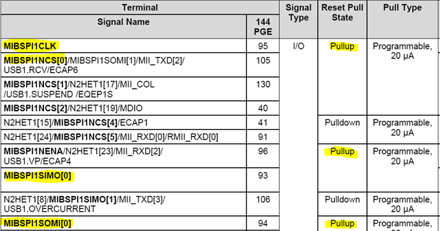
    However, due to the pull characteristics that the microcontroller has when it is in the Reset state during power-up, it acts as a current source with a value of 20 uA or 100 uA and has a different pull configuration during the reset state than the one desired. So, if a pin is pulled-down in the reset state and I need it to be pulled-up, then if I use an external 10 kohm resistor, the voltage on the pin will not be "0" (resistance pull-down resistor) but will be 3.1V due to the external pull-up resistor when the microcontroller is in reset state. For this reason, I am using a 4.7 Kohm pull-up resistor to get a voltage of 3.2 V (closer to 3.3 V). Any other considerations in the circuit such as capacitors?

    Best regards,

    Francisco.

  • HI Francisco,

    RM46Lx device has internal pull for SPI pins. The pull-type is configurable, and default is pull-up. I think the internal pull-up is sufficient for interfacing with SD card.

  • Hello QJ,

    I asked to texas instrument support if it was possible to configure the internal pull resistor when the device was in the RESET state, they told me it was not possible. Once it leaves this state, and enters the initialization state, it is possible to configure it, but while it is in the RESET state, it will have a fixed value of the internal pull resistors. For this reason, I need to use external pull resistor.

  • Hi Francisco,

    If you use MibSPI1/3/5, the SPI signals (CLK, CS0, MOSI, SIMO) are internally pulled up:

  • Hello QJ Wang,

    I can't use these pins because I also use the Ethernet module. However, this information is essential if in a future I use the RM46L852CZWTT, thank you.

    Regarding the subject of the resistors to be used, I could say that this topic is finished. However, I need to ask you what other features of my circuit I should consider in order to use continuous monitoring of the micro-SDXC in an industrial environment.

  • It depends on the SD card socket. for example, card detect (CD) pin. You can connect CD pin to MibSPI_nENA signal.

  • Hi QJ Wang,

    Yes, there are SD card sockets that has CD Detect when a memory card is inserted. One option would be to use the MibSPI_nENA pin. However, it could also be implemented through GPIO. In my case, I am using this second option because I use the SPI4 and USB module, so I need the pin USB_FUNC.PUENO instead of SPI4_ENA.

    On the other hand, I still have questions about what other features of my circuit I should consider in order to use continuous monitoring of the micro-SDXC in an industrial environment. For example, if it is necessary or not using capacitors for each pin and its value. The value of the capacitor between VCC and GND. It could be affected or not by EMI interference.

  • For SPI clock signal, if the signal trace long (transmission line), you can add a series termination at source. The series termination provides good signal quality by damping overshoot and undershoot, and effectively reducing line noise and EMI. Its drawbacks are that it slows the signal’s rise and fall time, and that it should not be used with distributed loads.  Where R = Trace impedance - driver output impedance.  


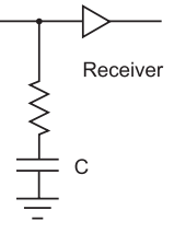
    Another termination method is to add a RC high-pass at the load end of the trace. AC termination is recommended for distributed loads, and clocks drivers. It generates no power dissipation. Where R = trace impedance. C=100pF is a good choice.

    .

  • Hello QJ Wang,

    However, If there is not much distance between the micro-SDXC and the SPI pins of the microcontroller, it should not be necessary to use these two circuits that you have recommended. Would this be true? What would be the maximum distance of the SPI transmission lines that should be between the microcontroller and the micro-SDXC?

  • If the trace length exceeds length tr/(2*tpd), the termination is required.

    where tr is the rise time of the pulse and tpd is the propagation delay of one inch of line. For FR-4 PCB material, the signal delay is around 1/6ns/inch. If the tr=5ns, the critical trace length = 5/(2*1/6) = 15 inches.

  • Hi QJ Wang,

    Thanks for your reply. This information is vital for my application.

    On the other hand, What value do you recommend me for the decoupling capacitor between VCC and GND? Would the value of 0.1uF be correct?

    Best regards,

    Francisco.

  • What value do you recommend me for the decoupling capacitor between VCC and GND? Would the value of 0.1uF be correct?

    A decoupling capacitor can take tiny voltage ripples, which could be harmful to IC, out of the voltage supply, and it can also act as a very small local power reservoir for IC. If the power supply temporarily drops its voltage, the decoupling capacitor can briefly supply power at the correct voltage.

    100nF or 0.1uF is a good choice for decoupling cap.

  • Hi QJ Wang,

    Any other consideration that I should take to use the micro SDXC High Endurance in addition to those already mentioned?

  • no more comments from my side.

  • Thanks QJ Wang.