Other Parts Discussed in Thread: EK-TM4C1294XL, EK-TM4C129EXL, UNIFLASH
Hi Community,
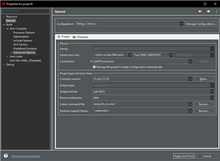
when i try to debug my code using ICDI in
Code Composer Studio
Version: 12.1.0.00007
i'm first time i got error as follows
CORTEX_M4_0: Trouble reading Memory Block at 0x40009008 on Page 0 of Length 0x04: Debug Port Error occurred.
the above error occurred for 2 time then get solve automatically after few hours i debugged previously older code it was working fine then
next day i get
CORTEX_M4_0: File Loader: Verification failed: Values at address 0x0000000000000000 do not match Please verify target memory and memory map.
This error got solved after some time. after that i tried to debug, i'm able to debug for few times like 3-4 time.
when I trying to debug code after all the above errors even i used JTAG following error occurs every time i try to debug
CORTEX_M4_0: Error connecting to the target.
i'm able to detect the device in device manager in Windows 10.
Board Jumper Status:
JP1 :
Booster Pack - connected,
OTG : connected.
ICDI : connected.
JP2 :
MCU3v3 : connected.
JP5:
UART : connected.

Previously i was able to debug the other code for the heap size: 0x800 and stack size : 1024, before occurrence of those errors as mentioned above.
after debugging the below code only i'm facing issue.
// This is Modified code of umda_demo using SPI/SSI communication
#include <stdint.h>
#include <stdbool.h>
#include <stdio.h>
#include "inc/hw_ints.h"
#include "inc/hw_memmap.h"
#include "inc/hw_types.h"
#include "inc/hw_ssi.h"
#include "driverlib/fpu.h"
#include "driverlib/gpio.h"
#include "driverlib/interrupt.h"
#include "driverlib/pin_map.h"
#include "driverlib/sysctl.h"
#include "driverlib/systick.h"
#include "driverlib/udma.h"
#include "driverlib/ssi.h"
#include "utils/cpu_usage.h"
#include "utils/ustdlib.h"
//****************************************************************************
//
// System clock rate in Hz.
//
//****************************************************************************
uint32_t g_ui32SysClock;
//*****************************************************************************
//
// The number of SysTick ticks per second used for the SysTick interrupt.
//
//*****************************************************************************
#define SYSTICKS_PER_SECOND 100
//*****************************************************************************
//
// The size of the memory transfer source and destination buffers (in words).
//
//*****************************************************************************
#define SSI_BUFFER_SIZE 256
//*****************************************************************************
//
// The SSI1 Buffers
//
//*****************************************************************************
static uint8_t g_ui8SSITxBuf[SSI_BUFFER_SIZE];
static uint8_t g_ui8SSIRxBuf[SSI_BUFFER_SIZE];
//*****************************************************************************
//
// The count of uDMA errors. This value is incremented by the uDMA error
// handler.
//
//*****************************************************************************
static uint32_t g_ui32uDMAErrCount = 0;
//*****************************************************************************
//
// The count of SSI1 buffers filled
//
//*****************************************************************************
static uint32_t g_ui32SSIRxCount = 0;
static uint32_t g_ui32SSITxCount = 0;
//*****************************************************************************
//
// The CPU usage in percent, in 16.16 fixed point format.
//
//*****************************************************************************
static uint32_t g_ui32CPUUsage;
//*****************************************************************************
//
// The number of seconds elapsed since the start of the program. This value is
// maintained by the SysTick interrupt handler.
//
//*****************************************************************************
static uint32_t g_ui32Seconds = 0;
//*****************************************************************************
//
// The control table used by the uDMA controller. This table must be aligned
// to a 1024 byte boundary.
//
//*****************************************************************************
#if defined(ewarm)
#pragma data_alignment=1024
uint8_t pui8ControlTable[1024];
#elif defined(ccs)
#pragma DATA_ALIGN(pui8ControlTable, 1024)
uint8_t pui8ControlTable[1024];
#else
uint8_t pui8ControlTable[1024] __attribute__ ((aligned(1024)));
#endif
//*****************************************************************************
//
// The error routine that is called if the driver library encounters an error.
//
//*****************************************************************************
#ifdef DEBUG
void
__error__(char *pcFilename, uint32_t ui32Line)
{
}
#endif
//*****************************************************************************
//
// The interrupt handler for the SysTick timer. This handler will increment a
// seconds counter whenever the appropriate number of ticks has occurred. It
// will also call the CPU usage tick function to find the CPU usage percent.
//
//*****************************************************************************
void SysTickHandler(void)
{
static uint32_t ui32TickCount = 0;
//
// Increment the tick counter.
//
ui32TickCount++;
//
// If the number of ticks per second has occurred, then increment the
// seconds counter.
//
if(!(ui32TickCount % SYSTICKS_PER_SECOND))
{
g_ui32Seconds++;
}
//
// Call the CPU usage tick function. This function will compute the amount
// of cycles used by the CPU since the last call and return the result in
// percent in fixed point 16.16 format.
//
g_ui32CPUUsage = CPUUsageTick();
}
//*****************************************************************************
//
// The interrupt handler for uDMA errors. This interrupt will occur if the
// uDMA encounters a bus error while trying to perform a transfer. This
// handler just increments a counter if an error occurs.
//
//*****************************************************************************
void uDMAErrorHandler(void)
{
uint32_t ui32Status;
//
// Check for uDMA error bit
//
ui32Status = uDMAErrorStatusGet();
//
// If there is a uDMA error, then clear the error and increment
// the error counter.
//
if(ui32Status)
{
uDMAErrorStatusClear();
g_ui32uDMAErrCount++;
}
}
//*****************************************************************************
//
// SSI1 Interrupt Handler
//
//*****************************************************************************
void SSI1IntHandler(void)
{
uint32_t ui32Status;
uint32_t ui32Mode;
ui32Status = SSIIntStatus(SSI1_BASE, 1);
SSIIntClear(SSI1_BASE, ui32Status);
ui32Mode = uDMAChannelModeGet(UDMA_CHANNEL_SSI1RX | UDMA_PRI_SELECT);
if(ui32Mode == UDMA_MODE_STOP)
{
g_ui32SSIRxCount++;
uDMAChannelTransferSet(UDMA_CHANNEL_SSI1RX | UDMA_PRI_SELECT,
UDMA_MODE_BASIC,
(void *)(SSI1_BASE + SSI_O_DR),
g_ui8SSIRxBuf, sizeof(g_ui8SSIRxBuf));
uDMAChannelEnable(UDMA_CHANNEL_SSI1RX);
}
if(!uDMAChannelIsEnabled(UDMA_CHANNEL_SSI1TX))
{
g_ui32SSITxCount++;
uDMAChannelTransferSet(UDMA_CHANNEL_SSI1TX | UDMA_PRI_SELECT,
UDMA_MODE_BASIC, g_ui8SSITxBuf,
(void *)(SSI1_BASE + SSI_O_DR),
sizeof(g_ui8SSITxBuf));
uDMAChannelEnable(UDMA_CHANNEL_SSI1TX);
}
}
void InitSPITransfer(void)
{
uint_fast16_t ui16Idx;
//
// Fill the TX buffer with a simple data pattern. 0 - 255
//
for(ui16Idx = 0; ui16Idx < SSI_BUFFER_SIZE; ui16Idx++)
{
g_ui8SSITxBuf[ui16Idx] = ui16Idx;
}
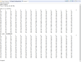
printf("data in Tx buffer:\n");
for(ui16Idx = 0; ui16Idx < SSI_BUFFER_SIZE; ui16Idx++)
{
if(ui16Idx > 0 && ui16Idx % 15 == 0)
printf("%x\n", g_ui8SSITxBuf[ui16Idx]);
else
printf("%x\t", g_ui8SSITxBuf[ui16Idx]);
}
//
// Enable the uDMA interface for both TX and RX channels.
//
SSIDMAEnable(SSI1_BASE, SSI_DMA_RX | SSI_DMA_TX);
//
// This register write will set the SSI1 to operate in loopback mode. Any
// data sent on the TX output will be received on the RX input.
//
//HWREG(SSI1_BASE + SSI_O_CR1) |= SSI_CR1_LBM;
SSILoopbackEnable(SSI1_BASE);
//****************************************************************************
//uDMA SSI1 RX
//****************************************************************************
//
// Put the attributes in a known state for the uDMA SSI1RX channel. These
// should already be disabled by default.
//
uDMAChannelAttributeDisable(UDMA_CHANNEL_SSI1RX,
UDMA_ATTR_USEBURST | UDMA_ATTR_ALTSELECT |
(UDMA_ATTR_HIGH_PRIORITY |
UDMA_ATTR_REQMASK));
//
// Configure the control parameters for the primary control structure for
// the SSIORX channel.
//
uDMAChannelControlSet(UDMA_CHANNEL_SSI1RX | UDMA_PRI_SELECT,
UDMA_SIZE_8 | UDMA_SRC_INC_NONE | UDMA_DST_INC_8 |
UDMA_ARB_4);
//
// Set up the transfer parameters for the SSI1RX Channel
//
uDMAChannelTransferSet(UDMA_CHANNEL_SSI1RX | UDMA_PRI_SELECT,
UDMA_MODE_BASIC,
(void *)(SSI1_BASE + SSI_O_DR),
g_ui8SSIRxBuf, sizeof(g_ui8SSIRxBuf));
//****************************************************************************
//uDMA SSI1 TX
//****************************************************************************
//
// Put the attributes in a known state for the uDMA SSI1TX channel. These
// should already be disabled by default.
//
uDMAChannelAttributeDisable(UDMA_CHANNEL_SSI1TX,
UDMA_ATTR_ALTSELECT |
UDMA_ATTR_HIGH_PRIORITY |
UDMA_ATTR_REQMASK);
//
// Set the USEBURST attribute for the uDMA SSI1TX channel. This will
// force the controller to always use a burst when transferring data from
// the TX buffer to the SSI1. This is somewhat more efficient bus usage
// than the default which allows single or burst transfers.
//
uDMAChannelAttributeEnable(UDMA_CHANNEL_SSI1TX, UDMA_ATTR_USEBURST);
//
// Configure the control parameters for the SSI1 TX.
//
uDMAChannelControlSet(UDMA_CHANNEL_SSI1TX | UDMA_PRI_SELECT,
UDMA_SIZE_8 | UDMA_SRC_INC_8 | UDMA_DST_INC_NONE |
UDMA_ARB_4);
//
// Set up the transfer parameters for the uDMA SSI1 TX channel. This will
// configure the transfer source and destination and the transfer size.
// Basic mode is used because the peripheral is making the uDMA transfer
// request. The source is the TX buffer and the destination is theUART0
// data register.
//
uDMAChannelTransferSet(UDMA_CHANNEL_SSI1TX | UDMA_PRI_SELECT,
UDMA_MODE_BASIC, g_ui8SSITxBuf,
(void *)(SSI1_BASE + SSI_O_DR),
sizeof(g_ui8SSITxBuf));
//
// Now both the uDMA SSI1 TX and RX channels are primed to start a
// transfer. As soon as the channels are enabled, the peripheral will
// issue a transfer request and the data transfers will begin.
//
uDMAChannelEnable(UDMA_CHANNEL_SSI1RX);
uDMAChannelEnable(UDMA_CHANNEL_SSI1TX);
//
// Enable the SSI1 DMA TX/RX interrupts.
//
SSIIntEnable(SSI1_BASE, SSI_DMATX | SSI_DMARX);
//
// Enable the SSI1 peripheral interrupts.
//
IntEnable(INT_SSI1);
}
void ConfigureSSI1(void)
{
uint32_t trashBin[1] = {0};
//
// Enable the SSI1 Peripheral.
//
SysCtlPeripheralEnable(SYSCTL_PERIPH_SSI1);
SysCtlPeripheralSleepEnable(SYSCTL_PERIPH_SSI1);
SysCtlPeripheralEnable(SYSCTL_PERIPH_GPIOB);
SysCtlPeripheralEnable(SYSCTL_PERIPH_GPIOE);
SysCtlPeripheralEnable(SYSCTL_PERIPH_GPIOP);
//
// Configure GPIO Pins for SSI1 mode.
//
GPIOPinConfigure(GPIO_PB4_SSI1FSS); //alternate function of a GPIO pins
GPIOPinConfigure(GPIO_PB5_SSI1CLK);
GPIOPinConfigure(GPIO_PE4_SSI1XDAT0);
GPIOPinTypeSSI(GPIO_PORTB_BASE, GPIO_PIN_5 | GPIO_PIN_4); //GPIO pin(s) for use by the SSI peripheral, pins are bit-packed bytes.
GPIOPinTypeSSI(GPIO_PORTE_BASE, GPIO_PIN_4);
SSIConfigSetExpClk(SSI1_BASE, g_ui32SysClock, SSI_FRF_MOTO_MODE_0,
SSI_MODE_MASTER, 1000000, 8);
SSIEnable(SSI1_BASE);
/* Clear SSI1 RX Buffer */
while (SSIDataGetNonBlocking(SSI1_BASE, &trashBin[0])) {}
}
//*****************************************************************************
//
// This example demonstrates how to use the uDMA controller to transfer data
// between memory buffers and to and from a peripheral, in this case a UART.
// The uDMA controller is configured to repeatedly transfer a block of data
// from one memory buffer to another. It is also set up to repeatedly copy a
// block of data from a buffer to the UART output. The UART data is looped
// back so the same data is received, and the uDMA controlled is configured to
// continuously receive the UART data using ping-pong buffers.
//
// The processor is put to sleep when it is not doing anything, and this allows
// collection of CPU usage data to see how much CPU is being used while the
// data transfers are ongoing.
//
//*****************************************************************************
int
main(void)
{
//
// Set the clocking to run directly from the crystal at 120MHz.
//
g_ui32SysClock = SysCtlClockFreqSet((SYSCTL_XTAL_25MHZ |
SYSCTL_OSC_MAIN |
SYSCTL_USE_PLL |
SYSCTL_CFG_VCO_480), 120000000);
printf("uDMA Example\n");
//
// Initialize SSI1.
//
ConfigureSSI1();
//
// Show the clock frequency on the display.
//
printf("Tiva C Series @ %u MHz\n\n", g_ui32SysClock / 1000000);
//
// Configure SysTick to occur 100 times per second, to use as a time
// reference. Enable SysTick to generate interrupts.
//
SysTickPeriodSet(g_ui32SysClock / SYSTICKS_PER_SECOND);
SysTickIntEnable();
SysTickEnable();
//
// Enable the uDMA controller at the system level. Enable it to continue
// to run while the processor is in sleep.
//
SysCtlPeripheralEnable(SYSCTL_PERIPH_UDMA);
//
// Enable the uDMA controller error interrupt. This interrupt will occur
// if there is a bus error during a transfer.
//
IntEnable(INT_UDMAERR);
//
// Enable the uDMA controller.
//
uDMAEnable();
//
// Point at the control table to use for channel control structures.
//
uDMAControlBaseSet(pui8ControlTable);
//
// Initialize the uDMA SPI transfers.
//
InitSPITransfer();
// Print transferred data on console
uint32_t var;
printf("Rx addr: %#p\n", g_ui8SSIRxBuf);
for(var = 0; var < SSI_BUFFER_SIZE; var++)
{
if(var > 0 && var % 15 == 0)
printf("%x\n", g_ui8SSIRxBuf[var]);
else
printf("%x\t", g_ui8SSIRxBuf[var]);
}
//
// Indicate on the display that the example is stopped.
//
printf("\nStopped\n");
IntDisable(INT_SSI1);
}
startup_css.c
//*****************************************************************************
//
// External declarations for the interrupt handlers used by the application.
//
//*****************************************************************************
extern void SysTickHandler(void);
extern void uDMAIntHandler(void);
extern void uDMAErrorHandler(void);
extern void SSI1IntHandler(void);
/*****************************************************************************
//
// The vector table. Note that the proper constructs must be placed on this to
// ensure that it ends up at physical address 0x0000.0000 or at the start of
// the program if located at a start address other than 0.
//
//*****************************************************************************
SysTickHandler, // The SysTick handler
SSI1IntHandler, // SSI1 Rx and Tx
I go through JTAG interface in Data sheet of TM4C129ENCPDT and community, if i'm not wrong LM FLASH PROGRAMMER may solve the problem.

Not able to get the User Register 0, User Register 1 to Debug Port Unlock
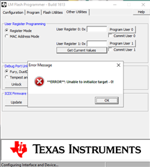
can i know what and why i'm facing this problem. what is solution for this?
Thanks and Best Regards,
Ajaykumar