This thread has been locked.

If you have a related question, please click the "Ask a related question" button in the top right corner. The newly created question will be automatically linked to this question.

TM4C123GH6PM: Cannot get reading from ADC

Part Number: TM4C123GH6PM
Other Parts Discussed in Thread: EK-TM4C123GXL

Hello,

I'm using TM4C123GH6PM launchpad to read an analog input and convert to digital. 

In settings, ADC0 is used, AIN0 (PE3) is the analogy voltage input. I use a trim to input 1.3V to PE3.

The IDE I used is IAR Arm 9.32.1.

I followed the TM4C123GH6PM Microcontroller datasheet, first initialize the ADC module, configure the Sample Sequencer, then go to the infinity while loop to sample voltage input.

In debug, I checked every register setting, they were set as coded. Unfortunately, the output is always 0x0dcd, there was no data converted.

Could anyone help me to check if I made some mistakes? 

Thank you!

The code is below:

#include <stdint.h>
#include "lm4f120h5qr.h"

int main()
{
unsigned int volatile adc_value = 0;

// ADC frequency initialization
SYSCTL_RCC_R &= ~(SYSCTL_RCC_PWRDN); // PLL Power Down
ADC0_CC_R |= ADC_CC_CS_PIOSC; // Set clock source: PIOSC
SYSCTL_RCC_R |= SYSCTL_RCC_PWRDN; // PLL Power On

// ADC Module Initialization
SYSCTL_RCGCADC_R |= SYSCTL_RCGCADC_R0; // Enable ADC0 Clock Gating
SYSCTL_RCGCGPIO_R |= SYSCTL_RCGCGPIO_R4; // Enable GPIO Port E Run Mode Clock Gating
GPIO_PORTE_DIR_R &= ~(1U << 3); // Set PE3 is an input
GPIO_PORTE_AFSEL_R |= (1U << 3); // Set PE3 functions as peripheral signal
GPIO_PORTE_DEN_R &= ~(1U << 3); // The digital function for PE3 is disabled
GPIO_PORTE_AMSEL_R |= (1U << 3); // Enable PE3 analog function

// ADC Sample Sequencer Configuration
ADC0_ACTSS_R &= ~(ADC_ACTSS_ASEN3); // ADC0 SS3 is Disabled
ADC0_EMUX_R |= ADC_EMUX_EM3_ALWAYS; // Set ADC0 SS3 triger as always (continuously sample)
ADC0_SSMUX3_R &= ~(ADC_SSMUX3_MUX0_M); // ADC SS3 first sample input select
ADC0_SSCTL3_R |= ADC_SSCTL3_IE0 | ADC_SSCTL3_END0; // 1st Sample is End of Sequence and set IE flag
ADC0_IM_R |= ADC_IM_MASK3; // SS3 Interrupt sent to interrupt controller
ADC0_ACTSS_R |= ADC_ACTSS_ASEN3; // ADC SS3 is Enabled

while (1) {
ADC0_PSSI_R |= ADC_PSSI_SS3; // Begin sampling on Sample Sequencer 3
while ((ADC0_RIS_R & ADC_RIS_INR3) == 0); // Wait while sample finish
adc_value = ADC0_SSFIFO3_R & 0xFFF; // Read conversion value from FIFO3
ADC0_ISC_R |= ADC_ISC_IN3; // SS3 Interrupt Status and Clear
}
}

  • Hi,

      First of all, please refer to FAQ #4 at https://e2e.ti.com/support/microcontrollers/arm-based-microcontrollers-group/arm-based-microcontrollers/f/arm-based-microcontrollers-forum/695568/faq-faqs-for-tm4c-arm-cortex-m4f-microcontrollers. Basically, we do not support DRM style of coding. TivaWare provides a rich set of APIs and examples to ease the software development. There is an example doing just what you need. You can refer to the example at C:\ti\TivaWare_C_Series-2.2.0.295\examples\peripherals\adc\single_ended.c. If you must use DRM coding style then you can refer to the ADC driver in C:\ti\TivaWare_C_Series-2.2.0.295\driverlib\adc.c on how the APIs are coded using DRM. APIs create a level of abstraction between the application code and the hardware. You can download TivaWare from https://www.ti.com/tool/SW-TM4C

      I will suggest you run the TivaWare example first and record all the ADC0 and GPIOE register settings and then compare with your own code. It will help you debug to know which registers in your code have been set differently than the example. That is likely to provide a clue. 

      Below is the example code that uses ADC0 to sample data on PE3. 

    #include <stdbool.h>
    #include <stdint.h>
    #include "inc/hw_memmap.h"
    #include "driverlib/adc.h"
    #include "driverlib/gpio.h"
    #include "driverlib/pin_map.h"
    #include "driverlib/sysctl.h"
    #include "driverlib/uart.h"
    #include "utils/uartstdio.h"
    
    //*****************************************************************************
    //
    //! \addtogroup adc_examples_list
    //! <h1>Single Ended ADC (single_ended)</h1>
    //!
    //! This example shows how to setup ADC0 as a single ended input and take a
    //! single sample on AIN0/PE3.
    //!
    //! This example uses the following peripherals and I/O signals.  You must
    //! review these and change as needed for your own board:
    //! - ADC0 peripheral
    //! - GPIO Port E peripheral (for AIN0 pin)
    //! - AIN0 - PE3
    //!
    //! The following UART signals are configured only for displaying console
    //! messages for this example.  These are not required for operation of the
    //! ADC.
    //! - UART0 peripheral
    //! - GPIO Port A peripheral (for UART0 pins)
    //! - UART0RX - PA0
    //! - UART0TX - PA1
    //!
    //! This example uses the following interrupt handlers.  To use this example
    //! in your own application you must add these interrupt handlers to your
    //! vector table.
    //! - None.
    //
    //*****************************************************************************
    
    //*****************************************************************************
    //
    // This function sets up UART0 to be used for a console to display information
    // as the example is running.
    //
    //*****************************************************************************
    void
    InitConsole(void)
    {
        //
        // Enable GPIO port A which is used for UART0 pins.
        // TODO: change this to whichever GPIO port you are using.
        //
        SysCtlPeripheralEnable(SYSCTL_PERIPH_GPIOA);
    
        //
        // Configure the pin muxing for UART0 functions on port A0 and A1.
        // This step is not necessary if your part does not support pin muxing.
        // TODO: change this to select the port/pin you are using.
        //
        GPIOPinConfigure(GPIO_PA0_U0RX);
        GPIOPinConfigure(GPIO_PA1_U0TX);
    
        //
        // Enable UART0 so that we can configure the clock.
        //
        SysCtlPeripheralEnable(SYSCTL_PERIPH_UART0);
    
        //
        // Use the internal 16MHz oscillator as the UART clock source.
        //
        UARTClockSourceSet(UART0_BASE, UART_CLOCK_PIOSC);
    
        //
        // Select the alternate (UART) function for these pins.
        // TODO: change this to select the port/pin you are using.
        //
        GPIOPinTypeUART(GPIO_PORTA_BASE, GPIO_PIN_0 | GPIO_PIN_1);
    
        //
        // Initialize the UART for console I/O.
        //
        UARTStdioConfig(0, 115200, 16000000);
    }
    
    //*****************************************************************************
    //
    // Configure ADC0 for a single-ended input and a single sample.  Once the
    // sample is ready, an interrupt flag will be set.  Using a polling method,
    // the data will be read then displayed on the console via UART0.
    //
    //*****************************************************************************
    int
    main(void)
    {
    #if defined(TARGET_IS_TM4C129_RA0) ||                                         \
        defined(TARGET_IS_TM4C129_RA1) ||                                         \
        defined(TARGET_IS_TM4C129_RA2)
        uint32_t ui32SysClock;
    #endif
    
        //
        // This array is used for storing the data read from the ADC FIFO. It
        // must be as large as the FIFO for the sequencer in use.  This example
        // uses sequence 3 which has a FIFO depth of 1.  If another sequence
        // was used with a deeper FIFO, then the array size must be changed.
        //
        uint32_t pui32ADC0Value[1];
    
        //
        // Set the clocking to run at 20 MHz (200 MHz / 10) using the PLL.  When
        // using the ADC, you must either use the PLL or supply a 16 MHz clock
        // source.
        // TODO: The SYSCTL_XTAL_ value must be changed to match the value of the
        // crystal on your board.
        //
    #if defined(TARGET_IS_TM4C129_RA0) ||                                         \
        defined(TARGET_IS_TM4C129_RA1) ||                                         \
        defined(TARGET_IS_TM4C129_RA2)
        //
        // Note: SYSCTL_CFG_VCO_240 is a new setting provided in TivaWare 2.2.x and
        // later to better reflect the actual VCO speed due to SYSCTL#22.
        //
        ui32SysClock = SysCtlClockFreqSet((SYSCTL_XTAL_25MHZ |
                                           SYSCTL_OSC_MAIN |
                                           SYSCTL_USE_PLL |
                                           SYSCTL_CFG_VCO_240), 20000000);
    #else
        SysCtlClockSet(SYSCTL_SYSDIV_10 | SYSCTL_USE_PLL | SYSCTL_OSC_MAIN |
                       SYSCTL_XTAL_16MHZ);
    #endif
    
        //
        // Set up the serial console to use for displaying messages.  This is
        // just for this example program and is not needed for ADC operation.
        //
        InitConsole();
    
        //
        // Display the setup on the console.
        //
        UARTprintf("ADC ->\n");
        UARTprintf("  Type: Single Ended\n");
        UARTprintf("  Samples: One\n");
        UARTprintf("  Update Rate: 250ms\n");
        UARTprintf("  Input Pin: AIN0/PE3\n\n");
    
        //
        // The ADC0 peripheral must be enabled for use.
        //
        SysCtlPeripheralEnable(SYSCTL_PERIPH_ADC0);
    
        //
        // For this example ADC0 is used with AIN0 on port E7.
        // The actual port and pins used may be different on your part, consult
        // the data sheet for more information.  GPIO port E needs to be enabled
        // so these pins can be used.
        // TODO: change this to whichever GPIO port you are using.
        //
        SysCtlPeripheralEnable(SYSCTL_PERIPH_GPIOE);
    
        //
        // Select the analog ADC function for these pins.
        // Consult the data sheet to see which functions are allocated per pin.
        // TODO: change this to select the port/pin you are using.
        //
        GPIOPinTypeADC(GPIO_PORTE_BASE, GPIO_PIN_3);
    
        //
        // Enable sample sequence 3 with a processor signal trigger.  Sequence 3
        // will do a single sample when the processor sends a signal to start the
        // conversion.  Each ADC module has 4 programmable sequences, sequence 0
        // to sequence 3.  This example is arbitrarily using sequence 3.
        //
        ADCSequenceConfigure(ADC0_BASE, 3, ADC_TRIGGER_PROCESSOR, 0);
    
        //
        // Configure step 0 on sequence 3.  Sample channel 0 (ADC_CTL_CH0) in
        // single-ended mode (default) and configure the interrupt flag
        // (ADC_CTL_IE) to be set when the sample is done.  Tell the ADC logic
        // that this is the last conversion on sequence 3 (ADC_CTL_END).  Sequence
        // 3 has only one programmable step.  Sequence 1 and 2 have 4 steps, and
        // sequence 0 has 8 programmable steps.  Since we are only doing a single
        // conversion using sequence 3 we will only configure step 0.  For more
        // information on the ADC sequences and steps, reference the datasheet.
        //
        ADCSequenceStepConfigure(ADC0_BASE, 3, 0, ADC_CTL_CH0 | ADC_CTL_IE |
                                 ADC_CTL_END);
    
        //
        // Since sample sequence 3 is now configured, it must be enabled.
        //
        ADCSequenceEnable(ADC0_BASE, 3);
    
        //
        // Clear the interrupt status flag.  This is done to make sure the
        // interrupt flag is cleared before we sample.
        //
        ADCIntClear(ADC0_BASE, 3);
    
        //
        // Sample AIN0 forever.  Display the value on the console.
        //
        while(1)
        {
            //
            // Trigger the ADC conversion.
            //
            ADCProcessorTrigger(ADC0_BASE, 3);
    
            //
            // Wait for conversion to be completed.
            //
            while(!ADCIntStatus(ADC0_BASE, 3, false))
            {
            }
    
            //
            // Clear the ADC interrupt flag.
            //
            ADCIntClear(ADC0_BASE, 3);
    
            //
            // Read ADC Value.
            //
            ADCSequenceDataGet(ADC0_BASE, 3, pui32ADC0Value);
    
            //
            // Display the AIN0 (PE3) digital value on the console.
            //
            UARTprintf("AIN0 = %4d\r", pui32ADC0Value[0]);
    
            //
            // This function provides a means of generating a constant length
            // delay.  The function delay (in cycles) = 3 * parameter.  Delay
            // 250ms arbitrarily.
            //
    #if defined(TARGET_IS_TM4C129_RA0) ||                                         \
        defined(TARGET_IS_TM4C129_RA1) ||                                         \
        defined(TARGET_IS_TM4C129_RA2)
            SysCtlDelay(ui32SysClock / 12);
    #else
            SysCtlDelay(SysCtlClockGet() / 12);
    #endif
        }
    }
    

  • Hi Charles,

    Thank you for your reply.

    I'm not prefer DRM coding style, I've tried to copy examples to run, unfortunately there were so many "no definition" errors. even I copied the include files in and added to the project, still didn't work. Follow some video tutorial,  I use the easiest way of coding to directly operate the dedicated registers, which is following the datasheet instructions.

    Today, I installed the TivaWare, tried to run the example from TivaWare. The manual for using example code in IAR is too simple, I cannot follow it.

    I copied project0 file, opened it, build it, errors.

    I'm pretty new to MCU coding, could you let me know the steps using TivaWare example code in IAR, from the very first step.

    Thank you very much!

  • Hi Kailiang,

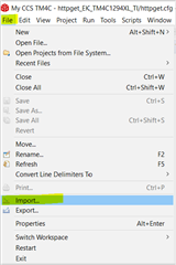
      I'm not familiar with IAR but it should be similar to CCS that allows you to simply import an example. In CCS, you simply just 'import' a project into your workspace. Please see below for CCS IDE.  


    There are bunch of TivaWare projects under C:\ti\TivaWare_C_Series-2.2.0.295\examples\boards\ek-tm4c123gxl.

     I will suggest you import a simple example like hello. Once you get hello example working you can just replace the hello.c with the C:\ti\TivaWare_C_Series-2.2.0.295\examples\peripherals\adc\single_ended.c and then rebuild the project again. Starting with an existing TivaWare example is the quickest way to start your software development. It will save you a lot time. If you don't have a pressing need to use DRM, then I will suggest you use TivaWare peripheral drivers for your software development. The TivaWare peripheral drivers are proven and have been extensively used by customers. 


  • Hi Charles,

    Thank you for the suggestions. 

    I will try CCS and import the examples.