


Other Parts Discussed in Thread: SYSCONFIG
Hello everyone
I'm currently working with the evalboard of the AM2634 microcontroller and experience an odd behavior regarding the watchdog timer. As a baseline, I'm using the boot sbl_qspi example project.
In my project, the setup of the watchdog is done in the SysConfig tool (running version 1.15) as shown below:
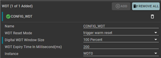
From the configuration, I would assume the watchdog to reset my controller after 200ms. While observing a toggling GPIO, the measurement shows, that the watchdog expires not earlier than 640 ms after the last clear signal was sent to the watchdog. How can this be?
I digged down into the generated .c files and noticed an entry in the ti_power_clock_config.c file, which sets up the clock frequencies for the different module in an array called gSocModulesClockFrequency[]. There, the clkRate value for the WDT0 is set to 5MHz. Where is this value coming from? Why is this 5MHz?
Further, I don't get, what the "Digital WDT Window Size" is for. Can you explain what this value is?
And finally, during debugging I believe to have stumbled over a bug in the MCU Plus SDK (version 08.05.00.24): (File soc_rcm.c, line 84) In the gXTALInfo array the Finp value gets initialized to the MHz value of the external oscillator (25000000Hz converted to 25MHz). But in the function SOC_rcmGetPeripheralClockFrequency (file soc_rcm.c, line 1702) this value is assumed to be in Hz. Where can I report this issue?
