This thread has been locked.

If you have a related question, please click the "Ask a related question" button in the top right corner. The newly created question will be automatically linked to this question.

RM46L852: How to use the IF2CMD bitfield (CAN)

Part Number: RM46L852
Other Parts Discussed in Thread: HALCOGEN, TMS570LC4357

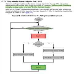
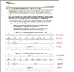
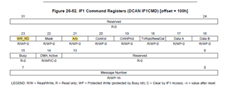
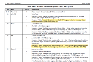
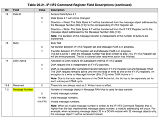
I'm trying to understand the IF2CMD register; more specifically the Message Number Field.

I do not understand where to find how to decode the value in this field in the documentation.

For example, to initialize a message box, HalCoGen use: 

canREG2->IF2CMD  = (uint8) 0xF8U;

To update ID, HalCoGen use 

node->IF2CMD = 0xA0U;

What's the full description of those bits?
How can I configure the If2CMD register to modify the IF2ARB bits to enable ISR?

Regards,
Gabriel

  • Hi Gabriel,

    Started working on your issue and will provide an update soon.

    --

    Thanks & regards,
    Jagadish.

  • Hi Gabriel,

    I will give you an overview of CAN message reception on transmission and CMD register purpose, you can go through the TRM for more details.

    The Message RAM in the CAN consists of message objects, these message objects should need to be configured before putting the CAN into operation.

    For example, as you can see the below pic.

    The message object-1 and 2 of CAN1 are configured for Transmission and Reception respectively with corresponding CAN ID.

    Similarly, message object-1 and 2 of CAN2 are configured for Transmission and Reception respectively with corresponding CAN ID.

    The above configuration indicates that the 123 ID message will be transmitted from message object-1 of CAN1 message RAM and it will be get transmitted into the message object-2 of CAN2 message RAM.

    And similarly, 456 ID message will be transmitted from message object-1 of CAN2 message RAM and it will be get transmitted into the message object-2 of CAN1 message RAM.

    The Interface Register sets control the CPU read and write accesses to the Message RAM. There are three interface registers IF1, IF2, and IF3. That means CPU can't access the message objects of message RAM directly, it will access through IF registers. For example, if CPU want to send 123 ID message from CAN1 then the message will be written to the IF register then from IF register the message will get moved to the message object-1 of CAN1 message RAM. Similarly, if CPU want to read the message that presents in message object-2 of CAN1 message RAM then it will ask to move message RAM to the IF register first and then from IF register the message will get moved to the application buffer.

    Here the data transfer to/from the message RAM from/to the IF register is initiated by the message number in the CMD register.

    Now keep above information in mind and verify the codes of canTransmit and canGetData functions in can.c and you will understand it better.

    Also please refer sections 27.2.3, 27.2.4, 27.2.5, 27.4.2.2, 27.5 and 27.6 for better understanding.

    --

    Thanks & regards,
    Jagadish.

  • Hi Jagasish,

    Thanks for your answer.


    I understand the role of IF2 and IF1 in the CAN configuration.
    What I don't understand is the meaning behind CMD.
    Can you show me where in the documentation you see the "message number" definition?

    For example, what does node->IF2CMD = 0xA0U; means?

    Also please refer sections 27.2.3, 27.2.4, 27.2.5, 27.4.2.2, 27.5 and 27.6 for better understanding.

    I don't understand why you are referring me to the SPI documentation when we are talking about the CAN.


    Are you talking about Technical Reference Manual SPNU514C ? 

    Thanks for your help.

    Regards,
    Gabriel

  • Hi Gabriel,

    The IF1/IF2 command registers shown in TRM further divided into 4 parts(Reserved, CMD, STAT and NO) in driver code as below

    For example, what does node->IF2CMD = 0xA0U; means?

    So, if we write IF2CMD means, we are writing into 16 to 23 bits of the command registers. So we are setting the 23rd and 21st bits by writing 0xA0.

    WR_RD=1 means selecting write operation, i.e. Transfer direction is from the IF1/IF2 register set to the message object addressed by Message Number (Bits [7:0]).

    Arb =1 and Write direction means: The Arbitration bits (Identifier + Dir + Xtd + MsgVal) will be transferred from the IF1/IF2 Register set to the message object addressed by Message Number (Bits [7:0]).

    Are you talking about Technical Reference Manual SPNU514C ? 

    Sorry my bad it is not the RM46 TRM and the sections i am referring are from TMS570LC4357 TRM.

    TMS570LC43x_TRM_spnu563a.pdf

    --

    Thanks & regards,
    Jagadish.

  • Ok, I think I get it.


    Contrary to other struct members like node->ES or node->ARB,  the node->IF2CMD does not actually represent the IF2CMD register.
    It represents only a slice of it: [16:23].

    This is why doing node->IF2CMD = 0xA0U will produce the equivalent of doing (0xA0 << 16).

    If this is correct, I'm closing this issue.

    Thanks a lot for your help, Jagadish.

    .

  • Hi Gabriel,

    It represents only a slice of it: [16:23].

    You are right.

    This is why doing node->IF2CMD = 0xA0U will produce the equivalent of doing (0xA0 << 16).

    Correct.

    --

    Thanks & regards,
    Jagadish.

  • Great. Thanks again for your help.