


Hello,
My individual code for basic I2C and SPI communication is working but when I'm trying to combine both, I'm not getting SPI clock and data (haven't checked I2C after combining yet).
My code snippet in main () function for combined I2C and SPI:
ui32SysClocks = SysCtlClockFreqSet((SYSCTL_XTAL_25MHZ | SYSCTL_OSC_MAIN | SYSCTL_USE_PLL | SYSCTL_CFG_VCO_480), 120000000);
InitConsole();
//initialize I2C module 0
InitI2C0();
// ioc_DIInit();
InitSPI();
SSIEnable(SSI0_BASE);
ui8Do_Source_Sink = 0x00;
pDO_Status[0] = true;
aui16SpiTxBuffer[0] = 0;
dataTX[0] = (HB_ENABLE << 0)| (HB_CONFIG << 0);//output high
SysCtlDelay(2000);//delay of
SPI_write(dataTX, 1);
The defintion of InitI2C0() is:
void InitI2C0(void)
{
//enable GPIO peripheral that contains I2C 0
SysCtlPeripheralEnable(SYSCTL_PERIPH_GPIOB);
//enable I2C module 0
SysCtlPeripheralEnable(SYSCTL_PERIPH_I2C0);
//reset module
SysCtlPeripheralReset(SYSCTL_PERIPH_I2C0);
// Configure the pin muxing for I2C0 functions on port B2 and B3.
GPIOPinConfigure(GPIO_PB2_I2C0SCL);
GPIOPinConfigure(GPIO_PB3_I2C0SDA);
// Select the I2C function for these pins.
GPIOPinTypeI2CSCL(GPIO_PORTB_BASE, GPIO_PIN_2);
GPIOPinTypeI2C(GPIO_PORTB_BASE, GPIO_PIN_3);
// Enable and initialize the I2C0 master module. Use the system clock for
// the I2C0 module. The last parameter sets the I2C data transfer rate.
// If false the data rate is set to 100kbps and if true the data rate will
// be set to 400kbps.
//I2CMasterInitExpClk(I2C0_BASE, SysCtlClockGet(), true);//for 400kbps tm4c123
I2CMasterInitExpClk(I2C0_BASE, SysCtlClockFreqSet((SYSCTL_XTAL_25MHZ | SYSCTL_OSC_MAIN | SYSCTL_USE_PLL | SYSCTL_CFG_VCO_480),120000000), true);//for 400kbps tm4c129
//clear I2C FIFOs
//HWREG(I2C0_BASE + I2C_O_FIFOCTL) = 80008000;
}
Definition of ioc_DIInit() :
void ioc_DIInit(void)
{
//i2cConfigbus stI2cConfig;
uint8_t aui8txBuffer[24];
uint8_t aui8rxBuffer[24];
uint8_t i;
uint16_t diSourceSink;
diSourceSink = 0x0;
// Configuring IO expander port as input for digital input and
// output for Source sink selection
aui8txBuffer[0] = 0x06;
aui8txBuffer[1] = 0x01;//Bit 1 for dig input 0
aui8txBuffer[2] = 0x00;//other bits are set as outputs including source/sink
I2CSend(DI_SLAVEADDRESS, 3, 0x06, 0x01, 0);//configuration port 0
// Configuring IO expander port as input for digital input and
// output for Source sink selection
aui8txBuffer[0] = 0x07;
aui8txBuffer[1] = 0x00;//
aui8txBuffer[2] = 0x00;//other bits are set as outputs including source/sink
I2CSend(DI_SLAVEADDRESS, 3, 0x07, 0x0, 0);//configuration port 1
SysCtlDelay(100);
/* Writing Source Sink Configuration to output registers port1 */
aui8txBuffer[0] = 0x03;
aui8txBuffer[1] = 0x00;
aui8txBuffer[2] = (diSourceSink << 7) & 0x80;//P17 (Bit 15) for source sink bit
I2CSend(DI_SLAVEADDRESS, 3, aui8txBuffer[0], aui8txBuffer[1] , aui8txBuffer[2] );//output reg 1
}
Definition for InitSPI():
void InitSPI(void){
SysCtlPeripheralEnable(SYSCTL_PERIPH_SSI0);
SysCtlPeripheralEnable(SYSCTL_PERIPH_GPIOA);
GPIOPinTypeGPIOOutput(GPIO_PORTA_BASE, GPIO_PIN_3|GPIO_PIN_2|GPIO_PIN_4);
GPIOPinTypeGPIOInput(GPIO_PORTA_BASE, GPIO_PIN_5);
SysCtlPeripheralEnable(SYSCTL_PERIPH_GPIOM);
//SysCtlPeripheralEnable(SYSCTL_PERIPH_GPIOB);
GPIOPinTypeGPIOOutput(GPIO_PORTM_BASE, GPIO_PIN_5);
GPIOPadConfigSet(GPIO_PORTM_BASE, GPIO_PIN_5, GPIO_STRENGTH_12MA, GPIO_PIN_TYPE_STD_WPU );
GPIOPinWrite(GPIO_PORTM_BASE, GPIO_PIN_5, GPIO_PIN_5);//PULL UP
//GPIOPinTypeGPIOOutput(GPIO_PORTB_BASE, GPIO_PIN_4);
//GPIOPadConfigSet(GPIO_PORTB_BASE, GPIO_PIN_4, GPIO_STRENGTH_12MA, GPIO_PIN_TYPE_STD_WPU );
//GPIOPinWrite(GPIO_PORTB_BASE, GPIO_PIN_4, GPIO_PIN_4);//PULL UP
GPIOPinConfigure(GPIO_PA2_SSI0CLK);
GPIOPinConfigure(GPIO_PA3_SSI0FSS);
GPIOPinConfigure(GPIO_PA4_SSI0XDAT0);//Tx
GPIOPinConfigure(GPIO_PA5_SSI0XDAT1);//Rx
GPIOPinTypeSSI(GPIO_PORTA_BASE, GPIO_PIN_5 | GPIO_PIN_4 | GPIO_PIN_3 | GPIO_PIN_2);
//SSIConfigSetExpClk(SSI0_BASE, ui32SysClocks, SSI_FRF_MOTO_MODE_2, SSI_MODE_MASTER, 40000000, 16);
//SSIConfigSetExpClk(SSI0_BASE, ui32SysClocks, SSI_FRF_MOTO_MODE_0, SSI_MODE_MASTER, 1500000, 16);
SSIConfigSetExpClk(SSI0_BASE, ui32SysClocks, SSI_FRF_MOTO_MODE_1, SSI_MODE_MASTER, 1500000, 16);//negative edge triggered
}
The SPI waveforms when the function ioc_DIInit() in main() is commented :
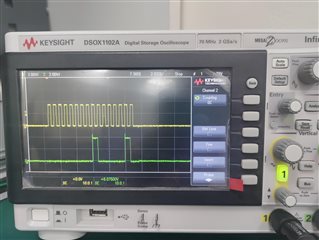
But when I uncomment ioc_DIInit(), I don't get the above waveforms.
These I2C and SPI functions work fine when run individually.
Please guide on why the SPI communication shouldn't work with the function ioc_DIInit(),i.e.when initiating I2C communication.
Best Regards,
Kiran
